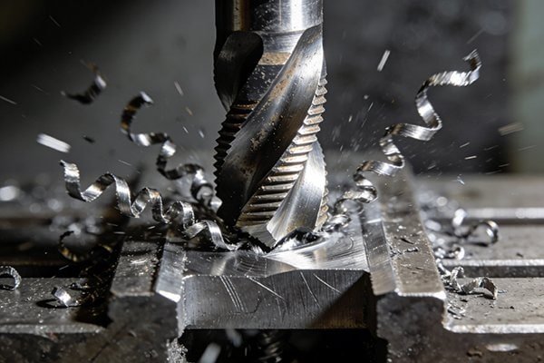
Choosing the wrong milling process can waste time and ruin parts. You need a clear strategy. This guide breaks down when to use face milling versus profile milling for perfect results.
Face milling is for creating large, flat surfaces by cutting with the bottom of the tool.1 Profile milling, or end milling, is for machining contours, grooves, and pockets by cutting with the side of the tool.2 The choice depends entirely on your final goal.
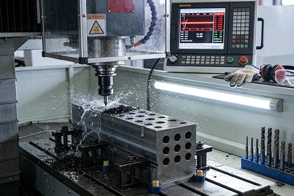
I’ve seen this question come up a lot in the thousands of machine shops we've worked with since 2012. It seems simple, but the difference between facing a part and milling a profile is fundamental to efficient and accurate machining. Getting it right saves you time, money, and headaches. Let's dive into the specifics so you can make the right call every time.
Where on the Tool is the Actual Cutting Happening?
You see the tool spinning, but do you know which edge is doing the work? Using the wrong part of the tool leads to poor finishes and premature wear.
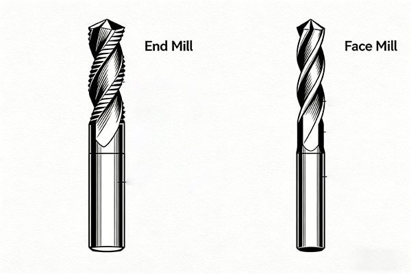
In face milling, the bottom cutting edges on the inserts do most of the work to create a flat plane. In profile milling, the circumferential side edges, or flutes, of the end mill are what engage the material to cut a contour.
Let's break this down further because it’s the core of the whole concept.
The Face Mill's Bottom-Edge Approach
A face mill is designed with multiple indexable inserts mounted on a large-diameter body.3 When it machines a surface, it's the bottom-most edge of these inserts that shears away the material. Think of it like a floor polisher; the entire bottom surface works in unison to create a single, flat plane. For an even better finish, we use special finishing or "wiper" inserts. These have a small flat section on the bottom edge that "irons out" the tiny ridges left by the other inserts, giving you an excellent surface finish even at high feed rates.4 This is why face milling is the king of flatness.
The End Mill's Side-Action
An end mill works completely differently. Its primary cutting action happens on its sides. The helical flutes on the body of the tool bite into the side of the material, carving out a path.5 This is how you create grooves, pockets, and vertical walls. The tool diameter is almost always smaller than the feature you are cutting. So, to machine a 20mm wide slot, you might use a 16mm end mill and take multiple side-cutting passes. It’s a process of tracing and carving, not broad-strokes surfacing.
| Operation | Primary Cutting Edge | Main Purpose |
|---|---|---|
| Face Milling | Bottom edge of inserts | Creating large, flat surfaces |
| Profile Milling | Side flutes of the tool | Machining contours and walls |
Is Your Goal Maximum Flatness or a Detailed Contour?
Your finished part isn't perfectly flat, or the details are sloppy. This means scrapped parts and wasted effort. You need to match your goal to the right machining process.
Choose face milling when your primary goal is achieving maximum flatness across a large area. If you need to create detailed contours, pockets, slots, or intricate shapes, you must use profile milling with an end mill.
Your goal for the feature dictates the tool and the process. One is about creating a perfect foundation, and the other is about building the complex structure on top of it.
The Quest for a Perfectly Flat Surface
When a customer needs a surface for a gasket or a mounting plate, flatness is everything. This is where face milling shines. The large diameter of the tool, combined with multiple cutting points, averages out any minor imperfections in the machine or the setup.6 The tool spans a wide area in a single pass. This action produces a consistently flat surface that is very difficult to achieve with a smaller tool. As I mentioned, using wiper inserts takes this to another level, essentially polishing the surface as it cuts. This is the most reliable way we know to get superior flatness and finish on a large plane.
Crafting Complex Contours
Now, think about making a mold cavity or the pocket in an aerospace part. Here, accuracy and detail are the priorities, not broad flatness. This is end mill territory. An end mill acts like a pen, precisely tracing the path laid out by the CNC program.7 Its smaller diameter allows it to get into tight corners and create sharp details. You can't carve a detailed logo with a giant paint roller, and you can't mill a complex pocket with a 100mm face mill. Profile milling is all about following a line, step-by-step, to create a feature with the exact dimensions and shape required by the design.
Why is Face Milling Built for Speed and End Milling for Finesse?
Are your machining jobs taking way too long to complete? Slow cycle times can destroy your profitability. You need to understand which process is fast and which is for detail.
Face milling is built for speed because its large diameter and multiple inserts remove a huge amount of material with each pass.8 End milling is for finesse, taking smaller, more controlled cuts to accurately create detailed features.
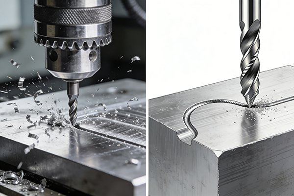
In our business, we always say there's a tool for every job, but it's also about the pace of the job. You wouldn't use a race car to navigate a tight parking garage.
Face Milling: The Bulldozer of Machining
When we need to clear a lot of material from the top of a block of steel, we grab a face mill. It's the "bulldozer" of our toolkit. The high number of cutting edges and the large diameter allow for a very high Metal Removal Rate (MRR).9 You can take a wide but relatively shallow cut and clear a surface in just a few passes. This is perfect for roughing operations or finishing large faces where cycle time is a critical factor. For our customers in the automotive industry, where every second counts, efficient face milling is essential to staying profitable.
End Milling: The Scalpel of Machining
End milling is a more delicate operation. It's our "scalpel." The process focuses on accuracy over raw speed.10 While you can use high-speed machining techniques with end mills, the volume of material removed per pass is much smaller compared to a face mill. The tool is carefully guided to trace complex toolpaths, often stepping down or over in very small increments. This controlled approach is necessary to achieve the tight tolerances and fine details required for molds, dies, and complex components. It might take longer, but the result is a level of detail and precision that face milling can never achieve.
How Does the Tool's Shape Limit the Features You Can Create?
You designed a part, but now you can't figure out how to machine it. The wrong tool choice can make a feature physically impossible to create. Let the tool's geometry guide you.
A large, wide face mill cannot create small pockets, sharp internal corners, or narrow slots.11 An end mill's small, cylindrical shape is specifically designed to create these detailed features, but it's very inefficient for large, open faces.
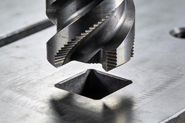
The physical shape of the tool is often the most important factor. It's a simple rule of geometry: you can't fit a square peg in a round hole, and you can't fit a giant tool into a tiny feature.
The Limits of a Face Mill
Think about a typical face mill from our catalog. It might be 80mm or 100mm in diameter. Its job is to machine wide, open surfaces. It is physically impossible for this tool to enter a 20mm wide slot or machine a corner with a 5mm radius. The tool body is simply too large. It is designed for one thing: creating flat planes. Trying to use it for detailed profile work is not only ineffective, it's impossible. Its shape is its biggest strength for its intended job, but it's also its biggest limitation for any other task.
The Versatility of an End Mill
An end mill, on the other hand, is defined by its smaller size and versatility. We offer them in countless diameters, from micro-tools smaller than a millimeter up to larger sizes. This variety allows you to select the perfect tool to create specific features.
| Feature to Machine | Possible with Face Mill? | Possible with End Mill? |
|---|---|---|
| 100mm wide flat top surface | Yes (Ideal) | Yes (but very slow) |
| 15mm wide slot | No | Yes (Ideal) |
| Internal pocket with 6mm corner radii | No | Yes (Ideal) |
| 3D contoured surface12 | No | Yes (with ball nose end mill) |
To make that 15mm slot, you would choose an end mill with a diameter smaller than 15mm, like 10mm or 12mm. The machine then uses side-cutting passes to achieve the final width. This is the essence of profile milling and why the end mill's shape is key to its function.
What is Your Primary Constraint: Cycle Time or Feature Accuracy?
Choosing between speed and precision is a daily challenge. Making the wrong trade-off hurts your bottom line. You must let your primary constraint guide your milling strategy.
If your main goal is to reduce cycle time by removing material quickly from a large surface, choose face milling. If feature accuracy and achieving a specific, detailed contour are your top priorities, then profile milling is the only choice.
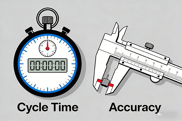
This final question brings everything together. When we consult with a new client, we always ask them to identify their main priority for the operation. The answer tells us exactly which process to recommend.
When Cycle Time is King
Imagine you're a manufacturer making thousands of engine blocks a day. Each block needs a perfectly flat head surface. Your constraint is time. You need to machine each part as quickly as possible. The clear winner here is face milling. You'd use a large face mill with roughing inserts to hog out the material, followed by a quick pass with wiper inserts for the finish. The goal is maximum material removal in minimum time. Profitability depends on speed, so face milling is the non-negotiable choice.
When Accuracy is Everything
Now, consider a job shop making a single, complex injection mold. The mold has intricate cavities, lifters, and cooling channels. The constraint here is absolute accuracy. The final part must be perfect, or the mold is useless. Time is secondary to precision. In this case, profile milling with various end mills is the required method. You might use a larger end mill for roughing out the pockets, then switch to a smaller ball nose end mill for the 3D surfacing, and finally a tiny end mill for fine details. Each step is chosen to ensure the final geometry is perfect. Here, finesse wins over speed every time. It’s important to remember that most complex parts require both processes: face milling to qualify the raw material, and then profile milling to create the final features.
Conclusion
Choosing correctly is simple. Use face milling for speed and large flat surfaces. Use profile milling with an end mill for detailed contours and features where accuracy is most important.
"MILLING OPERATIONS TYPES OF MILLING MACHINES", https://uhv.cheme.cmu.edu/procedures/machining/ch8.pdf. A manufacturing-process reference should define face milling as a milling operation used to produce flat surfaces, with cutting action occurring on the face of a rotating cutter whose axis is generally perpendicular to the work surface. Evidence role: definition; source type: education. Supports: Face milling is used to create large, flat surfaces and primarily cuts with the face of the cutter.. Scope note: The source may describe both face and peripheral cutting edges rather than only the “bottom” of the tool. ↩
"Overview: Pocket Milling", https://nuengr.unl.edu/durhamschool/elearning/Exercise4/index.htm?page=12. A machining handbook or educational source should describe end milling/profile milling as an operation in which the side cutting edges of an end mill machine slots, pockets, contours, and vertical surfaces. Evidence role: definition; source type: education. Supports: Profile milling or end milling is used to machine contours, grooves, and pockets with side-cutting edges.. Scope note: Terminology varies by source; some references distinguish profile milling from general end milling rather than treating them as identical. ↩
"Milling", https://mie.njit.edu/sites/mie/files/me215-24-fall2017.pdf. A machining-tool reference should document that face mills commonly use multiple replaceable or indexable inserts arranged around a cutter body to machine broad surfaces. Evidence role: definition; source type: education. Supports: Face mills are commonly large-diameter cutter bodies fitted with multiple indexable inserts.. Scope note: Not all face mills use indexable inserts; some small or specialized cutters may be solid or brazed designs. ↩
"An Experimental Study of Applying Various Cutting Edges on ...", https://www.academia.edu/86982794/An_Experimental_Study_of_Applying_Various_Cutting_Edges_on_Wiper_Milling_Inserts_in_Face_Milling_Aisi_1070_Steel. A machining research paper or tooling reference should explain that wiper inserts have modified edge geometry that reduces feed marks and can improve milled surface finish at higher feed rates. Evidence role: mechanism; source type: paper. Supports: Wiper inserts use a flat or modified edge to reduce ridges and improve surface finish at relatively high feed rates.. Scope note: The degree of surface-finish improvement depends on material, machine rigidity, cutter setup, and cutting parameters. ↩
"Helical - MACHINING GUIDEBOOK", https://web.mae.ufl.edu/designlab/Advanced%20Manufacturing/Helical_Machining_Guidebook.pdf. An educational machining source should describe end mills as tools with helical flutes and cutting edges along the periphery, enabling side cutting during slotting, contouring, and pocketing operations. Evidence role: mechanism; source type: education. Supports: End mills use helical side flutes to remove material along a programmed path.. Scope note: End mills may also have end-cutting capability; the citation would support the side-cutting role rather than exclude other cutting edges. ↩
"Improvement of Surface Flatness in Face Milling by Varying ... - Demos", https://demos.library.tamu.edu/scholars/display/n224491SE. A manufacturing reference should support the contextual point that face milling cutters with large diameters and multiple teeth are used to generate broad, flat surfaces with consistent surface finish. Evidence role: general_support; source type: education. Supports: Large, multi-tooth face mills can help produce consistent flat surfaces over broad areas.. Scope note: The “averages out imperfections” phrasing is an explanatory simplification; surface flatness also depends on machine alignment, fixturing, tool runout, and process parameters. ↩
"Tool Path Generation for Pocket Machining Operations with ...", https://www.academia.edu/100136748/Tool_Path_Generation_for_Pocket_Machining_Operations_with_Island. A CNC machining reference should explain that end mills follow programmed toolpaths to machine profiles, pockets, and contours, supporting the analogy that they trace geometry specified by the CNC program. Evidence role: mechanism; source type: education. Supports: End mills follow CNC-programmed toolpaths to create detailed contours and pockets.. Scope note: The “pen” comparison is illustrative; actual toolpaths incorporate cutter compensation, stepovers, depths of cut, and machine dynamics. ↩
"Milling", https://mie.njit.edu/sites/mie/files/me215-24-fall2017.pdf. A machining reference or research source should state that face milling can achieve high material-removal rates because wide cutters with multiple teeth remove material across a broad engagement width. Evidence role: mechanism; source type: education. Supports: Face milling can remove material quickly because large, multi-insert cutters engage a wide area per pass.. Scope note: Actual removal rate depends on spindle power, feed rate, depth of cut, work material, tooling, and machine rigidity. ↩
"Milling Equations", https://www.montana.edu/jdavis/met314/documents/homework/Milling%20Examples.pdf. A manufacturing-engineering source should define material removal rate and explain that milling MRR is determined by feed, width of cut, and depth of cut, giving context for why large face mills with many teeth can remove material rapidly. Evidence role: mechanism; source type: education. Supports: Large-diameter, multi-edge face mills can support high material removal rates under suitable cutting parameters.. Scope note: The formula supports the relationship between engagement and MRR, but it does not by itself prove that every face-milling setup achieves high MRR. ↩
"The Effect of the Machining Strategy on the Surface Accuracy ...", https://www.academia.edu/164656395/The_Effect_of_the_Machining_Strategy_on_the_Surface_Accuracy_When_Milling_with_a_Ball_End_Cutting_Tool_of_the_Aluminum_Alloy_AlCu4Mg. A CNC machining or manufacturing-process reference should describe profile/end milling as suitable for producing detailed features such as pockets, slots, and contours where toolpath control and dimensional accuracy are important. Evidence role: general_support; source type: education. Supports: End milling/profile milling is commonly used when controlled geometry and feature accuracy are more important than broad-area material removal.. Scope note: The source would support the typical application emphasis, not a universal trade-off; end milling can also be optimized for high-speed roughing. ↩
"CNC machining: The complete engineering guide", https://gab.wallawalla.edu/~ralph.stirling/classes/engr480/examples/nvx/NVX/Helpful%20Docs/CNC_Machining_The_Complete_Engineering_Guide.pdf. A machining reference should support that cutter diameter and geometry constrain the minimum slot width, pocket access, and internal corner radius that can be machined with a rotating milling cutter. Evidence role: mechanism; source type: education. Supports: Large face mills are geometrically unsuitable for small pockets, sharp internal corners, and narrow slots.. Scope note: The statement is generally true for conventional milling access, but special tooling, alternative setups, or non-milling processes may create features that a large face mill cannot. ↩
"Simulation of Ball-nose End Milling Operations", https://www.academia.edu/33096377/Simulation_of_Ball_nose_End_Milling_Operations_Selection_of_Geometric_Resolution_Parameters. A CNC machining source should describe ball-nose end mills as tools used for three-dimensional contouring and sculptured-surface machining because their rounded tips can machine complex curved surfaces. Evidence role: definition; source type: education. Supports: Ball-nose end mills are used to machine 3D contoured surfaces.. Scope note: The citation supports the tool’s suitability for 3D contouring, while final surface quality also depends on step-over, toolpath strategy, and machine accuracy. ↩