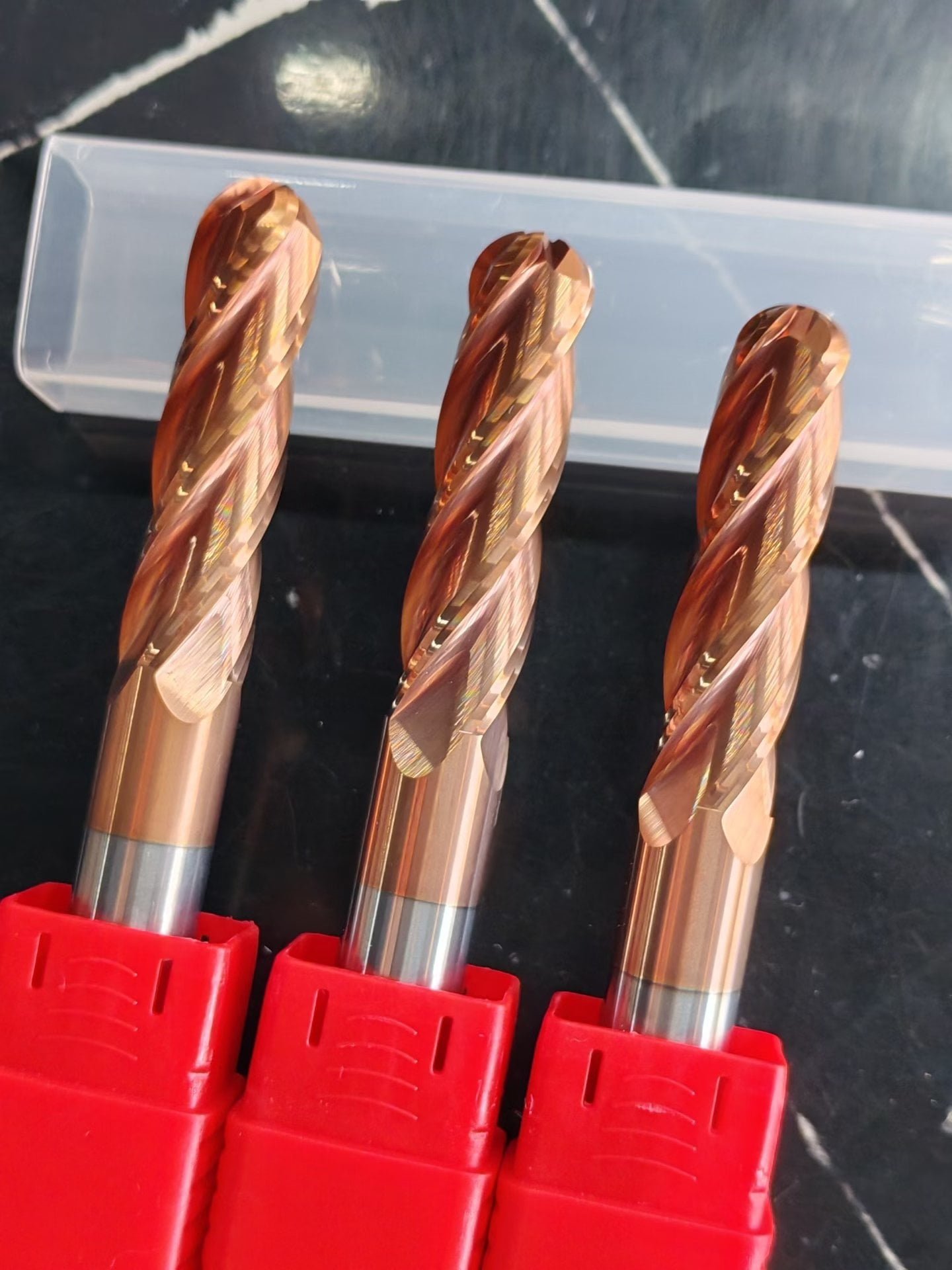
Struggling to pick the right ball end mill diameter? Making the wrong choice can lead to poor finishes or slow cycle times, costing you both time and money.
The right ball end mill diameter depends on your part's smallest corner radius, your surface finish goals, and your specific operation1. For roughing, use the largest diameter possible. For finishing, select a tool smaller than the tightest corner, balancing detail access with machining efficiency.
Choosing the right tool is more than just grabbing one that looks about right from the drawer. It’s a strategic decision that directly impacts how efficiently you work and the quality of your final product. Getting this right from the start saves a lot of headaches later on. Let's break down the key factors so you can make the best choice every time.
Should I Use a Large or a Small Diameter?
Are you stuck deciding between a large tool for speed and a small tool for detail? This choice can make or break your job, either doubling your time or ruining the part.
For roughing and semi-finishing, always use the largest diameter possible to maximize the material removal rate2. For finishing, the best choice is the largest diameter that can still fit into all the part's features3, as this will give you the best surface finish in the shortest time.
When I'm planning a 3D milling job, my first thought is always about efficiency versus detail. These two goals often pull in opposite directions, and the tool diameter is right in the middle of it. For removing a lot of material quickly, nothing beats a large, robust tool. It's more stable and can handle much higher feed rates.4 But when it comes to the final pass, the game changes. A large tool might be faster on open, gentle curves, but it's useless if it can't get into the small pockets and tight corners. This is where you have to balance the need for speed with the part's geometry.
Large vs. Small Diameter Trade-offs
| Feature | Large Diameter Tool | Small Diameter Tool |
|---|---|---|
| Primary Use | Roughing, Semi-Finishing | Finishing, Detailing, Engraving |
| Material Removal Rate | High | Low |
| Finishing Speed | Faster on open surfaces | Slower due to small stepover |
| Access to Details | Limited | Excellent |
| Tool Stability | High | Lower (prone to deflection)5 |
How Does My Part's Smallest Corner Dictate My Tool Size?
Have you ever programmed a job only to find your tool is too big for the corners? This forces you to stop the machine and find another tool, wasting valuable setup time.
Your ball end mill's radius must be smaller than the smallest internal corner radius6 on your part. A tool with a radius equal to or larger than the corner will cause chatter, poor finish, and high tool pressure7. A good rule is to pick a tool diameter around 70-90% of the corner diameter.
I learned this lesson the hard way early in my career. I was working on a complex mold, and I tried to use a 10mm ball end mill to finish a 5mm internal radius (a 10mm corner). The noise from the chatter was terrible, and the finish looked awful. The tool was engaging with too much surface area at once, creating massive cutting forces. It's like trying to clean the sharp inside corner of a box with a big, round sponge—it just won't fit. The tool needs some clearance to cut effectively without binding up.
The Rule of Thumb for Corner Radii
The most important rule is to never use a tool with the exact same radius as the corner you are cutting. If your CAD drawing shows a 6mm internal radius, the absolute largest tool you should consider is a 10mm or 11mm diameter ball end mill, but an 8mm would be much safer. This ensures that the tool cuts with a smaller point of contact, reducing engagement angle and pressure8. This simple check before you even start programming will prevent chatter, extend your tool life, and give you a much better surface finish.
How Does Diameter Affect My Final Surface Finish?
Are you chasing that perfect, smooth surface on your 3D parts? The wrong tool diameter can leave ugly ridges, no matter how small you make your stepover.
A larger diameter ball end mill creates a shallower scallop for the same stepover distance9 compared to a smaller tool. This allows you to achieve a smoother surface with a larger stepover, which can dramatically reduce your cycle time10 while still hitting your quality target.
Think about the ridges, or scallops, left between each pass of the tool. The height of these scallops is what determines how smooth the surface feels and looks. A larger tool is naturally flatter at its cutting point. Because of this flatter profile, the cusp it leaves behind is much wider and shallower. A small tool, being much more curved, leaves a deeper and sharper cusp for the same stepover. This means to get the same beautiful finish with a 6mm ball end mill, you might need a 0.1mm stepover. But with a 12mm ball end mill, you could get that same finish with a 0.2mm stepover, cutting your finishing time in half.
Balancing Diameter and Stepover
For any given surface finish requirement (scallop height), a larger tool will always be more efficient.
| Tool Diameter | Stepover for Same Scallop Height | Relative Cycle Time |
|---|---|---|
| 6mm | 0.1mm | Slow |
| 12mm | 0.2mm | Medium |
| 20mm | 0.35mm | Fast |
This relationship is why for finishing large, open areas like in automotive molds or aerospace components, we always select the largest ball end mill that the part geometry allows. It's the fastest way to get a high-quality finish.
What's the 2-Tool Strategy for Most 3D Jobs?
Do you feel like you are constantly stopping to change tools when milling complex surfaces? This approach wastes time and makes programming more complicated than it needs to be.
The most efficient method is a two-tool strategy. First, use a large ball end mill to semi-finish the entire part. Then, use a smaller ball end mill for a "rest machining11" operation, which only cuts the areas the first tool could not reach, like tight corners.
This is the standard operating procedure in any serious mold and die shop, and it’s something we use all the time. Instead of trying to find one "perfect" tool for the whole job, which doesn't exist, we split the work. We let each tool do what it does best. This approach is built into modern CAM software and is incredibly powerful for reducing machining time while achieving fantastic detail. It simplifies programming and makes the whole process more predictable and efficient.
Step 1: The Workhorse Tool
Your first tool is the largest ball end mill that makes sense for the overall part. Its job is to machine 95% of the surface quickly and efficiently. We call this the workhorse because it does the majority of the heavy lifting for the finishing stage. It establishes the main contours and leaves a consistent, small amount of material for the next step.
Step 2: The Detail Tool
This is where the magic happens. Using a feature in your CAM software called "rest machining" (or "remachining"), you tell the software which tool you used first. It then automatically calculates all the areas—and only those areas—where the first tool was too big to fit. It then generates a toolpath for your smaller, detail tool to clean up just those remaining spots. This is extremely efficient because you aren't re-cutting surfaces that are already finished.
Conclusion
Choosing the right ball end mill is a balance. Start with the largest tool possible for efficiency, but always let your part's smallest corner and finish needs guide your final choice.
"[PDF] Milling cutter software architecture for force and surface finish ...", https://scholars.unh.edu/cgi/viewcontent.cgi?article=1516&context=dissertation. A machining text or university manufacturing resource should support that cutter selection is constrained by part geometry, required surface finish, and the operation type; this is general process-planning support rather than a formula for one specific tool diameter. Evidence role: general_support; source type: education. Supports: The appropriate ball end mill diameter depends on the part’s smallest corner radius, desired surface finish, and machining operation.. Scope note: Contextual support; the source may discuss milling cutter selection broadly rather than ball end mills alone. ↩
"[PDF] MATERIAL REMOVAL PROCESSES", https://www.egr.msu.edu/~pkwon/me478/machining.pdf. A manufacturing or machining reference should support that larger-diameter milling cutters can generally remove material at higher rates because they permit greater engagement and more robust cutting parameters; actual material-removal rate remains limited by machine power, tool material, setup rigidity, and workpiece material. Evidence role: mechanism; source type: education. Supports: For roughing and semi-finishing, a larger-diameter ball end mill generally improves material removal rate.. Scope note: General support; it does not prove that the largest possible tool is optimal in every setup. ↩
"11.1.2 NC machining - MIT", https://web.mit.edu/hyperbook/Patrikalakis-Maekawa-Cho/node213.html. A CAM or machining textbook should support that finishing-tool diameter is limited by accessibility to small features such as fillets, pockets, and internal radii; this supports the geometric constraint but not a universal optimum for every finish strategy. Evidence role: mechanism; source type: education. Supports: For finishing, the selected ball end mill must be small enough to access all required part features.. Scope note: Contextual support; toolpath strategy, holder clearance, and machine dynamics can also constrain tool choice. ↩
"[PDF] COMPENSATION OF TOOL FORCES IN SMALL DIAMETER END ...", https://pec.ncsu.edu/wp-content/uploads/sites/10/2015/03/aspe1999_abstract.pdf. A machining dynamics source should support that cutter and tool assembly stiffness increase with diameter and overhang conditions, reducing deflection and permitting more aggressive cutting parameters when other constraints are unchanged. Evidence role: mechanism; source type: paper. Supports: Larger-diameter tools are generally more stable and can support higher feed rates than smaller tools under comparable conditions.. Scope note: Support is conditional; feed rate also depends on tool material, flute geometry, spindle power, workpiece material, and fixturing. ↩
"Compensation for Deflection of Miniature Milling Tools", https://pec.ncsu.edu/research/compensation-for-deflection-of-miniature-milling-tools/. A machining mechanics reference should support that smaller end mills are more susceptible to elastic deflection because cutting-tool stiffness is strongly affected by diameter and unsupported length. Evidence role: mechanism; source type: education. Supports: Small-diameter ball end mills have lower stability and are more prone to deflection.. Scope note: The source would support the mechanical tendency, not the exact deflection expected in a specific machine setup. ↩
"Mill Tooling Guide - Purdue University", https://www.purdue.edu/bidc/resources/metal-working/mill-tooling-guide/. A machining or CAM reference should support that an end mill must have a radius smaller than the internal fillet or corner radius it is intended to machine, because a cutter cannot produce an internal radius smaller than its own effective radius. Evidence role: mechanism; source type: education. Supports: A ball end mill radius should be smaller than the smallest internal corner radius that it must machine.. Scope note: This supports the geometric accessibility constraint; finishing allowance and toolpath tolerance may require additional clearance. ↩
"Chatter Avoidance by Spindle Speed and Orientation ...", https://asmedigitalcollection.asme.org/manufacturingscience/article/146/2/021006/1168978/Chatter-Avoidance-by-Spindle-Speed-and-Orientation. A milling dynamics source should support that excessive cutter engagement and contact in corners can increase cutting forces and promote chatter, which degrades surface finish. Evidence role: mechanism; source type: paper. Supports: Using a ball end mill radius equal to or larger than the internal corner radius can increase cutting forces, chatter risk, and poor surface finish.. Scope note: The source may discuss chatter and engagement generally rather than the exact case of a ball end mill matching an internal corner radius. ↩
"Path Interval and Its Relevance to Cutting Force in Ball and ...", https://www.astrj.com/pdf-143051-71308?filename=Path-Interval-and-Its-Rel.pdf. A milling mechanics source should support that lower radial engagement and contact angle generally reduce cutting forces in milling; this supports the mechanism behind choosing a smaller cutter for internal corners. Evidence role: mechanism; source type: paper. Supports: Using a smaller tool in a corner can reduce engagement angle and cutting pressure.. Scope note: The source may not address the exact 8 mm versus 10 mm example, only the broader relationship between engagement and force. ↩
"Surface Quality Enhancement by Constant Scallop-Height in Three ...", https://www.academia.edu/115331766/Surface_Quality_Enhancement_by_Constant_Scallop_Height_in_Three_Axis_Milling_Operations. A ball-end milling surface-generation paper or manufacturing textbook should support that scallop height is a geometric function of tool radius and stepover, with larger tool radii producing lower cusp heights for the same stepover on comparable surfaces. Evidence role: mechanism; source type: paper. Supports: For the same stepover, a larger-diameter ball end mill produces a shallower scallop height than a smaller one.. Scope note: The relationship is exact only under simplified geometric assumptions; surface slope, tool tilt, runout, and machine dynamics can affect actual roughness. ↩
"[PDF] STL-based Finish Machining of Rapid Manufactured Parts and Tools", https://repositories.lib.utexas.edu/bitstreams/e48fd4f8-3411-4e26-991a-f60fcc2cccd1/download. A CAM or machining reference should support that increasing permissible stepover reduces the number of parallel finishing passes and can reduce machining time; this supports the direction of the effect, while the magnitude depends on toolpath length, acceleration, feed rate, and non-cutting moves. Evidence role: mechanism; source type: education. Supports: Using a larger stepover for the same surface-finish target can reduce finishing cycle time.. Scope note: Does not establish a specific percentage reduction for all jobs. ↩
"CAM Basics 1.2 - Tool controls - University of Maryland", https://dozuki.umd.edu/Guide/CAM+Basics+1.2+-+Tool+controls/178. A CAM textbook or neutral educational source should define rest machining as a strategy that identifies material left by a previous larger tool and generates subsequent toolpaths to remove the remaining material with a smaller tool. Evidence role: definition; source type: education. Supports: Rest machining uses a smaller tool to machine areas left uncut or inaccessible after a previous toolpath.. Scope note: This supports the definition of the strategy, not that a two-tool process is always the most efficient option. ↩