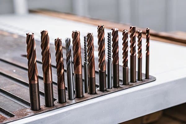
Are you confused about what an end mill can really do? Using the wrong tool wastes time and material. This guide breaks down its core capabilities for you.
An end mill is a versatile cutting tool used to create a wide range of features1. You can use it for facing flat surfaces, shouldering 90-degree steps, pocketing internal cavities, contouring part profiles, and machining complex 3D curved surfaces2. It's the workhorse of any CNC mill.
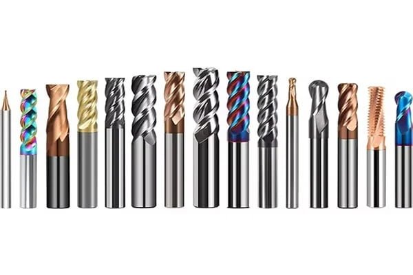
To really get the most out of your machine, you need to know more than just what an end mill can do. You need to understand how it does it. This knowledge is the foundation for choosing the right tool and strategy for every job you run in our shop. Let's start with the most fundamental question.
How Does an End Mill Cut Material in the First Place?
Do you just see an end mill as a spinning drill bit? This misunderstanding leads to poor cuts and broken tools. Understand its unique cutting action to improve your machining.
An end mill cuts material with its rotating helical flutes3. The cutting edges on its side (peripheral) and end (face)4 shear away chips as the tool moves along a programmed path. This dual-action capability is what allows it to create such precise features.
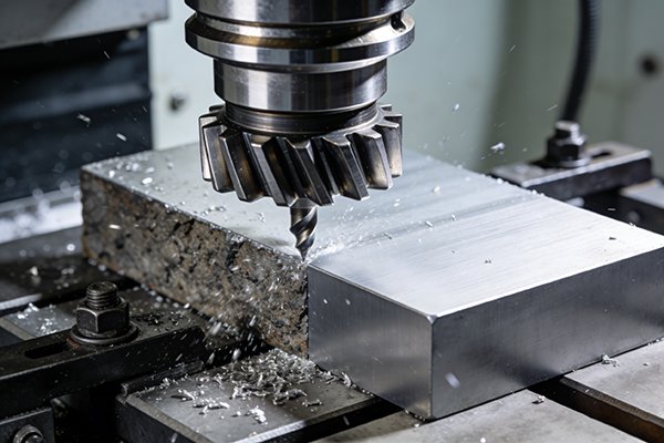
When I first started in this business over a decade ago, I saw an end mill as just a stronger drill bit. I quickly learned that was a costly mistake. A drill is designed to plunge straight down. An end mill is designed to cut sideways.5 This is the key difference that makes it so powerful. The magic is in its design, specifically how it uses its flutes for two distinct cutting actions.
The Role of Flutes
The helical grooves you see spiraling up an end mill are called flutes.6 They serve two critical purposes. First, the edge of the flute is the actual cutting edge that shears the material. Second, the groove itself acts as a channel to evacuate the chips7 that are created. Clearing chips effectively is just as important as cutting, as it prevents tool breakage and ensures a good surface finish. The number of flutes—from two for aluminum to four or more for steel8—is chosen based on the material and the type of operation.
Cutting Actions Explained
Because an end mill has cutting edges on both its sides and its face, it can perform two primary types of milling. Understanding this is everything.
| Cutting Action | Where it Cuts | Common Use Case |
|---|---|---|
| Peripheral Milling | On the side of the tool | Cutting a slot, shaping an outside profile (contouring) |
| Face Milling | On the end/bottom of the tool | Creating a flat surface, machining the floor of a pocket |
This combination is what makes the end mill the most versatile tool in our shop. It can move side-to-side, up-and-down, and diagonally, all while cutting material precisely.
How Do I Machine a Perfectly Flat Surface or Step?
Are your surfaces uneven or your steps not perfectly 90 degrees? This ruins part accuracy and forces you to do extra finishing work. Master facing and shouldering for flawless results.
To get a perfectly flat surface, use a "facing" operation with a flat-bottom end mill. To create a sharp, 90-degree step, use a "shouldering" operation, where the side of the end mill cuts the vertical wall while the bottom of the tool machines the floor.
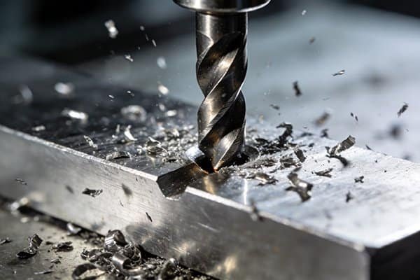
Every quality part starts with a good foundation. In machining, that foundation is often a perfectly flat reference surface. If your first surface isn't flat, every subsequent operation will have errors. That's why mastering facing and shouldering is a non-negotiable skill. I've seen many jobs fail because the initial prep work was rushed. These two simple operations are your solution to achieving that critical geometric accuracy right from the start.
Facing for Ultimate Flatness
Facing is the process of making the top surface of your raw material perfectly flat and smooth. Think of it like mowing a lawn. The end mill moves back and forth across the entire surface, taking off a thin layer of material with each pass. The best tool for this job is a standard flat-bottom end mill. For very large surfaces, we often switch to a dedicated face mill with indexable inserts9, like our Series B tools, because they are more efficient and cost-effective. The toolpath strategy is also important. A "zig-zag" path is fast, but a "one-way" path often gives a better, more consistent surface finish.
Shouldering for Perfect 90-Degree Steps
A shoulder is any feature that has a vertical wall meeting a horizontal floor, ideally at a perfect 90-degree angle. This is an incredibly common feature in all sorts of parts, from machine components to molds. This operation uses both the side and the bottom of the end mill simultaneously. The side of the tool (peripheral cutting) creates the clean vertical wall, while the bottom of the tool (face cutting) machines the flat floor. The standard flat end mill is the go-to tool for this. The sharpness of the inside corner is determined by the tool itself; a standard end mill gives you a sharp corner, while a round nose end mill would leave a small radius.
How Do I Carve Out Pockets and Cut Out Profiles?
Need to hollow out a section or cut a specific shape? Guessing the right approach can be slow and inefficient. Learn the difference between pocketing and contouring, the two most common tasks.
Use "pocketing" to remove material from an inside boundary, like carving a recess. Use "contouring" (or profiling) to follow an outside or inside line, cutting out a part's shape. Both operations rely heavily on the end mill's powerful side-cutting ability.
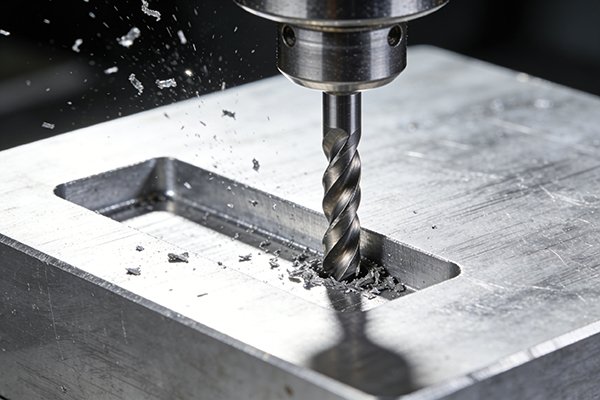
Once you have a flat surface, the real work of shaping your part begins. Almost every part we make for our clients in the automotive, aerospace, or mold-making industries involves some form of pocketing or contouring. These are the true workhorse operations of an end mill. They are how you turn a simple block of metal into a functional component with specific features and dimensions. Let's break down how each one works.
Pocketing: Removing Material Inside a Boundary
Pocketing is exactly what it sounds like: creating a pocket or cavity inside a part. You define a boundary, and the end mill clears out all the material inside it down to a specific depth. The process usually starts with the end mill plunging or, more commonly, "ramping" down into the material to avoid the heavy load of a straight plunge. From there, it follows a specific toolpath, like a spiral or a high-speed adaptive path, to efficiently clear the material. For roughing out large pockets quickly, we often use a roughing end mill (also called a corn cob mill) because its serrated edges break chips into smaller pieces10, allowing for very aggressive cuts. Then, we come back with a standard flat end mill for a clean finish on the walls and floor.
Contouring: Following the Line to Define a Shape
Contouring, also known as profiling, is the operation you use to cut the final outline of your part from the stock material. The end mill simply follows a 2D line or curve, cutting along the path. This is how you get the outside shape of a component. But it's not just for outside profiles. Contouring can also be used to machine a precise slot or trace an internal shape after a pocket has been roughed out. The choice of tool is critical here. A flat end mill creates a sharp corner at the bottom of the wall, while a ball end mill or round nose end mill would be used if the design calls for a curved transition between the wall and the floor.
How Are Complex, Curved 3D Surfaces Machined?
Your parts require smooth, organic shapes, not just flat surfaces. Using the wrong tool or strategy results in rough, stepped surfaces that need hours of hand-finishing.
Complex 3D surfaces are created using "surfacing" toolpaths. A ball end mill moves in tiny, closely-spaced steps across the surface. The round tip creates a smooth, flowing finish, much like a 3D printer builds up layers, but by removing material instead.

Many of the parts we produce, especially for the mold & die and aerospace industries, are not made of simple flat surfaces and straight lines. They have complex, flowing, organic curves. Machining these shapes is an art form known as 3D surfacing or 3D milling. This is where the true capability of a 5-axis CNC machine and the right end mill really shines. It's how we create everything from the contoured cavities of an injection mold to the aerodynamic surfaces of an aerospace component.
The Essential Role of the Ball End Mill
You cannot machine a smooth, curved surface with a flat end mill. It will leave a "stair-step" effect that looks terrible and is dimensionally inaccurate. The hero of 3D surfacing is the ball end mill. Its perfectly hemispherical tip means that no matter the angle of the surface, the tool makes contact with a consistent, round profile. This allows it to blend passes together seamlessly, creating a smooth finish without any sharp edges. It follows a complex toolpath generated by CAM software, moving in the X, Y, and Z axes simultaneously to trace the 3D model of the part.
Understanding "Stepover" for a Perfect Finish
The key to a glass-smooth surface finish in 3D milling is a parameter called "stepover." This is the distance the tool moves over between each parallel cutting pass. The relationship between stepover, speed, and quality is a critical trade-off we manage every day.
| Stepover Size | Machining Time | Surface Finish |
|---|---|---|
| Small | Longer | Smoother (fewer scallops) |
| Large | Shorter | Rougher (more scallops) |
A very small stepover means the passes overlap significantly, which minimizes the tiny ridges (called scallops) left between passes, resulting in a surface that might not even need polishing. However, this takes a very long time. For roughing out 3D shapes, we use a larger stepover to remove material quickly, then follow up with a finishing pass using a small stepover and a high-quality ball end mill.
So, Which Operation Should I Choose for My Part?
Facing all these options can be overwhelming for a new machinist or a purchasing manager. Choosing the wrong operation wastes time and can scrap a valuable part.
Start by identifying the feature you need to create. Is it a flat top surface? Use facing. A hollowed-out area? Use pocketing. An outer shape? Use contouring. A curved surface? Use 3D surfacing with a ball end mill. Match the operation to the feature.
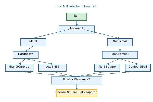
After more than a decade in this business, I know that the secret to efficiency and quality is making the right decision before the machine even starts. For our customers, who are often large-scale manufacturers and distributors, time is money, and scrap is a disaster. Choosing the correct operation and tool is the first and most important step in process planning. To make it simple, I've broken down the decision-making process into a straightforward guide.
What Is Your Goal?
Look at the blueprint or 3D model of your part. Isolate a single feature you need to create. Is it a flat plane? A hole? A curved surface? A sharp edge that needs to be broken? Answering this question is the first step. Once you know what you want to achieve, you can select the correct operation.
A Step-by-Step Decision Guide
Use this table as a quick reference. We train all our new engineers and consult with our clients using this same logic. It removes the guesswork and sets you on the right path.
| If your goal is to... | Then you need this operation... | And the primary tool is a... |
|---|---|---|
| Create a flat top surface on the raw material. | Facing | Flat End Mill / Face Mill |
| Create a 90-degree step or vertical wall. | Shouldering | Flat End Mill |
| Hollow out a recess or internal area. | Pocketing | Flat End Mill (or a Rougher) |
| Cut out the final outline of a part. | Contouring / Profiling | Flat End Mill |
| Machine a smooth, curved, or organic shape. | 3D Surfacing | Ball End Mill |
| Add a 45-degree angle to break a sharp edge. | Chamfering | Chamfer End Mill |
| Create a radius on an edge. | Corner Rounding | Corner Rounding End Mill |
By following this simple logic, you can confidently plan your operations, select the right tools from our catalog, and achieve precise, high-quality results every time.
Conclusion
From flat surfaces to complex 3D curves, the end mill is incredibly versatile. Understanding facing, pocketing, and surfacing unlocks its full potential for creating almost any machined part.
"CNC milling – 2-axis operations – pocketing", https://sites.wit.edu/soad-labs/cnc-milling-2-axis-operations-pocketing/. A machining reference or manufacturing textbook source should support that end mills are used for multiple milling operations, including profiling, slotting, pocketing, and surface generation. Evidence role: general_support; source type: education. Supports: An end mill is a versatile cutting tool used to create a wide range of features.. Scope note: This would support the general versatility of end mills rather than proving every listed use case in every material or machine setup. ↩
"(PDF) Comparative Study of Tool Path Strategies in NX for Pocket ...", https://www.academia.edu/94541570/Comparative_Study_of_Tool_Path_Strategies_in_NX_for_Pocket_Machining. A manufacturing-process reference should document that milling cutters, including end mills, are commonly applied to face milling, shoulder milling, pocketing, profile milling, and freeform or contour surface machining. Evidence role: definition; source type: education. Supports: End mills can be used for facing, shouldering, pocketing, contouring, and 3D surface machining.. Scope note: The source may describe these as milling operations generally, so the citation would contextualize rather than independently validate every tool choice in the article. ↩
"[PDF] Cutting Load Capacity of End Mills with Complex Geometry", https://research.sabanciuniv.edu/231/1/3011800000736.pdf. A machining reference should explain that end mills have helical flutes whose cutting edges remove material and whose geometry affects chip evacuation and cutting action. Evidence role: mechanism; source type: education. Supports: An end mill cuts material with rotating helical flutes.. Scope note: Specific flute geometry varies by tool design, so the source would support the general mechanism rather than a universal geometry for all end mills. ↩
"[PDF] Milling", https://mie.njit.edu/sites/mie/files/me215-24-fall2017.pdf. A technical machining source should support that end mills can have cutting edges on both the periphery and the end face, enabling peripheral and end-cutting operations. Evidence role: mechanism; source type: education. Supports: End mills cut with side and end cutting edges.. Scope note: Some end mills are not center-cutting or have specialized geometries, so the support should be framed as applying to common end mill designs. ↩
"On the machinability of medium density fiberboard by drilling", https://bioresources.cnr.ncsu.edu/resources/on-the-machinability-of-medium-density-fiberboard-by-drilling/. A manufacturing reference should distinguish drilling, which primarily produces holes by axial feed, from milling, where rotating cutters remove material through lateral or multi-axis feed motions. Evidence role: definition; source type: education. Supports: Drills are primarily for axial hole-making, while end mills are designed for lateral milling cuts.. Scope note: Certain end mills can plunge and certain drills can perform limited specialized operations, so the citation should support the general distinction between drilling and milling, not an absolute rule. ↩
"Mill Tooling Guide - Purdue University", https://www.purdue.edu/bidc/resources/metal-working/mill-tooling-guide/. A cutting-tool reference should define flutes as the helical grooves on an end mill that form cutting edges and provide space for chip flow. Evidence role: definition; source type: education. Supports: The spiral grooves on an end mill are called flutes.. Scope note: The exact helix angle and flute form depend on tool type and application. ↩
"Mill Tooling Guide - Purdue University", https://www.purdue.edu/bidc/resources/metal-working/mill-tooling-guide/. A machining source should support that flutes provide chip space and aid chip evacuation during milling, which is important for cutting performance and tool life. Evidence role: mechanism; source type: education. Supports: Flutes channel chips away from the cutting zone.. Scope note: Chip evacuation effectiveness also depends on coolant, toolpath, material, and cutting parameters. ↩
"Upright Mill Use Did You Know", https://hydrogen.wsu.edu/2017/09/11/upright-mill-use-did-you-know/. A machining handbook or university reference should support the general practice that lower flute counts are often used for materials requiring larger chip space, such as aluminum, while higher flute counts are common for steels and harder materials. Evidence role: expert_consensus; source type: education. Supports: Two-flute end mills are commonly selected for aluminum, while four or more flutes are often used for steel.. Scope note: Optimal flute count depends on machine rigidity, tool coating, diameter, engagement, and application, so this should be treated as a rule of thumb rather than a universal standard. ↩
"[PDF] Milling", https://mie.njit.edu/sites/mie/files/me215-24-fall2017.pdf. A machining reference should support that face mills, often using indexable inserts, are commonly used for efficient machining of broad flat surfaces. Evidence role: general_support; source type: education. Supports: Dedicated indexable face mills are often used for large flat surfaces.. Scope note: The source would support the general use of indexable face mills, not the cost-effectiveness of any specific proprietary tool series. ↩
"[PDF] Cutting Load Capacity of End Mills with Complex Geometry", https://research.sabanciuniv.edu/231/1/3011800000736.pdf. A cutting-tool reference should support that roughing end mills use serrated or chipbreaker cutting edges to divide chips into smaller segments and permit higher material-removal rates in roughing operations. Evidence role: mechanism; source type: education. Supports: Roughing end mills have serrated edges that break chips into smaller pieces.. Scope note: The achievable aggressiveness depends on work material, tool geometry, machine power, and cutting parameters. ↩