Struggling with metric vs. inch end mills? This confusion can lead to scrapped parts and broken tools. I'll show you how to get it right every time.
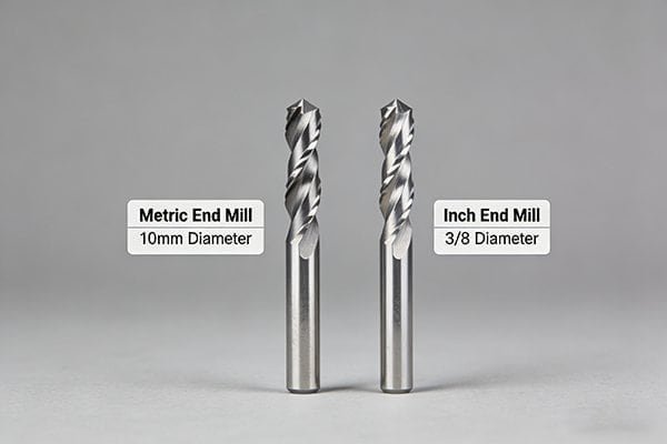
Choosing between a metric or inch end mill depends on your engineering drawing. Always match the tool's unit system to the drawing's specifications. If the drawing is metric, use a metric tool. If it's imperial, use an inch tool. This prevents costly machining errors.
It sounds simple, but the real world gets messy with different machines, old drawings, and global supply chains. As a tool manufacturer, I've seen these small mistakes cause huge headaches for machine shops. Let's break down the common problems I see and how you can avoid them, starting with the most important rule of all.
What's the #1 Rule That Overrides Everything Else? (Hint: Check Your Drawing First)
You have a new job, but which end mill do you grab from the drawer? Choosing wrong wastes time and money. Let's establish the one rule that simplifies this entire process.
The number one rule is to always follow the engineering drawing. The drawing is your contract for the part.1 If it specifies dimensions in millimeters, use metric tools. If it specifies dimensions in inches, use imperial (inch) tools. Don't guess or try to convert.

I can't stress this enough: the drawing is your single source of truth. It contains the design intent from the engineer. A feature designed as 1/2 inch was meant to be exactly 12.7 mm, not "around 12 or 13 mm." Trying to substitute can cause a cascade of problems. I once worked with a shop that tried to machine a part with metric dimensions using inch tools they already had. They thought "close enough" would work. But the slight differences in size meant none of the final parts passed inspection. They had to scrap the entire batch and start over, a very costly lesson. The drawing's unit system dictates the tolerances.2 For example, a ϕ10H7 hole has a very specific tolerance range that is defined in the metric system.3 You simply cannot achieve that precision by trying to use a tool that is "almost" the right size.
| Dimension on Drawing | Correct Tool | Incorrect "Close" Tool | Potential Problem |
|---|---|---|---|
| 1/2" (12.7 mm) | 1/2" End Mill | 12 mm End Mill | Feature is undersized by 0.7 mm |
| 10 mm | 10 mm End Mill | 3/8" (9.525 mm) End Mill | Feature is undersized by 0.475 mm |
Always respect the drawing. It will save you from making simple but expensive mistakes.
My Drawing Is Metric, But My Machine Uses Inch Collets. Now What?
Your drawing clearly says 10mm, but your tool holder only takes inch sizes like 1/2" or 3/8". This mismatch is a common headache. It can stop a job cold if you're not prepared.
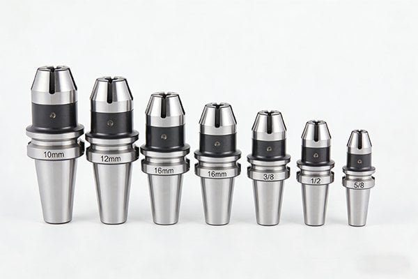
If your drawing is metric but your machine uses inch collets, you must use the correct tool holder or adapter. Never force a metric shank into an inch collet or vice versa.4 The best solution is to use a metric-sized collet that fits your existing tool holder system.
This is a classic problem, especially in shops with a mix of older and newer equipment. A collet is designed to clamp onto a tool shank with very high precision and force.5 For it to work correctly, the fit has to be perfect. Trying to force a 12mm shank into a 1/2" (12.7mm) collet will not work. Even worse is trying to squeeze a 1/2" shank into a 12mm collet. You might damage the collet, reducing its clamping ability forever. A poor fit leads to tool runout, which ruins surface finish and drastically shortens tool life.6 In the worst-case scenario, the tool could slip during a heavy cut or even pull out of the holder completely7, creating a very dangerous situation.
So, what is the right way to handle this?
- Get Metric Collets: Most modern tool holding systems, like ER collets (ER16, ER32, etc.), are available in a full range of metric sizes.8 This is the best and safest solution. Simply buy the correct metric collet for your inch-based holder.
- Use an Adapter: In some cases, a sleeve or adapter can be used, but this can sometimes add to your tool runout. I always recommend getting the right collet first.
Never compromise on how you hold your tools.
Can't I Just Use a 6mm End Mill for a 1/4" (6.35mm)9 Job?
The numbers look close on paper. Using a 6mm end mill for a 1/4" slot seems like a harmless shortcut, right? This small difference of 0.35mm can cause big problems and ruin your final part.
No, you cannot substitute a 6mm end mill for a 1/4" (6.35mm) job. The 0.35mm difference will leave material on the walls of your feature, causing the part to be out of tolerance. Always use the exact tool size specified by your CAM program and drawing.
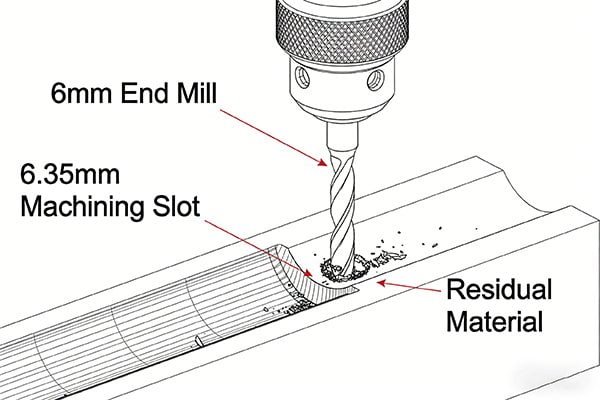
This issue goes straight to the heart of CNC programming. When your CAM software generates a toolpath, it bases all its calculations on the exact tool diameter you entered.10 If you tell the software you are using a 1/4" (6.35mm) tool, it will calculate its path to create a perfect 1/4" slot. If you then put a 6mm tool in the machine, the machine will follow that same path, but the smaller tool won't clear out all the material.11 You'll be left with a step of 0.175mm on each side of the slot. Your slot will be too narrow, and your part will be a reject. This is not something you can easily fix later. This problem gets even worse with more complex shapes, like internal pockets or corner radii, where the wrong tool size will completely distort the final geometry.
| Programmed Action | Tool Used | Actual Result |
|---|---|---|
| Cut 1/4" (6.35mm) slot | 1/4" (6.35mm) End Mill | Perfect 6.35mm slot |
| Cut 1/4" (6.35mm) slot | 6mm End Mill | 6.175mm slot (undersized) |
| Cut 6mm slot | 1/4" (6.35mm) End Mill | 6.35mm slot (oversized) |
The rule is simple: the tool in the spindle must perfectly match the tool defined in the program. No exceptions.
Beyond Diameter, What Other Sizes Do I Need to Get Right?
You've carefully matched the cutting diameter to the drawing, but the tool still doesn't work. What gives? There are other critical dimensions that must be correct for a successful job.
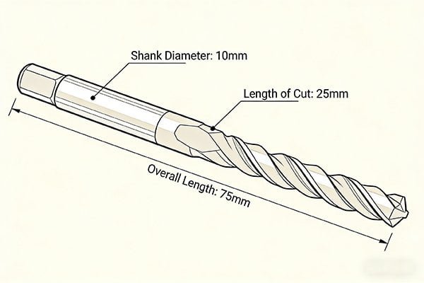
Besides the cutting diameter, you must match the shank diameter to your tool holder. Also, ensure the length of cut (flute length) is long enough for the feature's depth, and the overall length is sufficient to avoid a collision with the workpiece or fixtures.
Getting the cutting diameter right is only the first step. I've seen machinists get stuck because they overlooked these other equally important measurements. Let's break them down.
1. Shank Diameter
This goes right back to our discussion about collets. The shank is the part of the tool that goes into the holder. Metric end mills have metric shanks (e.g., 6mm, 10mm, 12mm). Inch end mills have inch shanks (e.g., 1/4", 3/8", 1/2"). They are not interchangeable. You must ensure the shank diameter of your tool is an exact match for your collet or tool holder.
2. Length of Cut (LOC)
This is the length of the flutes on the side of the end mill. Your length of cut must be longer than the depth of the feature you are machining. If you are cutting a slot that is 20mm deep, you need a tool with at least 20mm of LOC. If you use a tool with only 15mm of LOC, the non-fluted shank will start rubbing against the wall of your part, causing friction, heat, and damage to both the tool and the workpiece.12
3. Overall Length (OAL)
This is the total length of the tool from tip to tail. The tool needs to be long enough to reach the area you are cutting without the tool holder or the machine's spindle crashing into the part or the clamps holding it down. Always check for clearance before you hit the cycle start button.
Can You Give Me a Simple Flowchart to Make the Right Choice Every Time?
Feeling overwhelmed by all the details? It can be easy to make a mistake, especially when you are under pressure to get a job running. To help, I've created a simple decision-making process that you can follow every time.
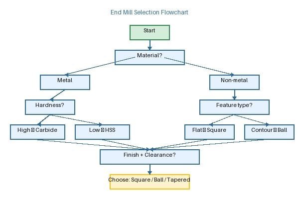
To choose the right end mill, first check the drawing for the unit system (metric/inch). Next, match the tool's cutting diameter to the drawing's feature size. Then, verify the shank diameter fits your collet. Finally, confirm the length of cut and overall length are adequate.
Think of this as your pre-flight checklist before you start any milling job. By following these steps in order, you can methodically and safely choose the perfect tool and avoid nearly all common errors.
Here is the process I use:
-
START HERE -> Check the Drawing: What unit system is it in? Millimeters or inches? This is your guide for the entire process. If the drawing is metric, you will be looking for a metric tool. If it's in inches, you need an inch tool.
-
Match the Cutting Diameter: Find the specific feature you need to machine (e.g., a slot, a pocket). What is its specified size? Your tool's cutting diameter must match this dimension exactly. For a 10mm slot, you need a 10mm end mill.
-
Match the Shank Diameter: Look at your tool holder or collet. What size is it designed to hold? The shank of your chosen end mill must be an exact match. Do not mix a 12mm shank with a 1/2" collet.
-
Check the Length of Cut (LOC): How deep do you need to machine? Your end mill's LOC must be greater than this depth to prevent the shank from rubbing on the workpiece.
-
Check the Overall Length (OAL): Is the part held in a vise? Are there clamps in the way? Your tool's OAL must be long enough to reach the cutting area without any part of the machine or holder colliding with the setup.
If you can answer "yes" to all these checks, you have the right tool for the job.
Conclusion
The drawing always dictates your choice. Matching the tool's diameter, shank, and length to the drawing and your machine setup prevents errors, saving you time, money, and frustration.
"[PDF] ENGINEERING DRAWING STANDARDS MANUAL - S3VI - NASA", https://s3vi.ndc.nasa.gov/ssri-kb/static/resources/NASA%20GSFC-X-673-64-1F.pdf. Engineering drawing standards describe technical drawings as the formal means for communicating product geometry, dimensions, tolerances, and other requirements, supporting the treatment of the drawing as the governing specification for manufacture and inspection. Evidence role: expert_consensus; source type: institution. Supports: The engineering drawing is the governing specification for the part.. Scope note: This supports the general role of drawings in engineering communication; legal contractual status depends on the purchase order and governing contract terms. ↩
"Engineering Metrology Toolbox", https://emtoolbox.nist.gov/. ISO and ASME drawing practices define dimensions and tolerances within the stated units of the drawing, so the specified unit system is part of the dimensional requirement interpreted by manufacturing and inspection personnel. Evidence role: definition; source type: institution. Supports: The unit system on an engineering drawing governs how tolerances should be interpreted.. Scope note: The source would establish standards practice; it may not address every shop-specific convention or dual-dimension drawing format. ↩
"Engineering fit - Wikipedia", https://en.wikipedia.org/wiki/Engineering_fit. ISO 286 defines the system of limits and fits, including tolerance grades such as H7 for nominal metric sizes, supporting the claim that a 10 mm H7 hole corresponds to a specified dimensional tolerance zone. Evidence role: definition; source type: institution. Supports: A ϕ10H7 hole has a defined tolerance range in the ISO metric limits-and-fits system.. Scope note: The precise numerical limits depend on the nominal size range and edition of the standard; secondary summaries should be checked against the applicable ISO standard in production work. ↩
"050011 D Standard ER11 collets, DIN 6499 / ISO 15488, diameter at ...", https://www.tadaahshop.com/en/050011-d-standard-er11-collets-din-6499-iso-15488-diameter-at-your-choice.html. Collet standards and manufacturer-independent technical references specify nominal clamping diameters and limited clamping ranges for collets, supporting the need to match the tool shank diameter to the collet size rather than forcing mismatched units. Evidence role: mechanism; source type: institution. Supports: Metric and inch shanks should not be forced into mismatched collets because collets are designed for specified clamping diameters and ranges.. Scope note: Exact allowable collapse range varies by collet type and standard, so the source should be matched to the holder system being used. ↩
"CNC Collets: Types and Maintenance Tips - Techniks", https://www.techniksusa.com/cnc-collets-types-and-maintenance-tips-techniks/. Machining and toolholding references describe collets as workholding or toolholding devices that grip cylindrical shanks concentrically by elastic deformation, supporting the description of their precision clamping function. Evidence role: definition; source type: education. Supports: A collet is a precision clamping device for cylindrical tool shanks.. Scope note: The degree of precision and clamping force depends on the collet type, condition, nut, holder, and tightening torque. ↩
"Effect of Machining Parameters and Tool Wear on Surface ... - PMC", https://pmc.ncbi.nlm.nih.gov/articles/PMC6187721/. Experimental machining studies report that tool runout changes chip load distribution and is associated with poorer surface finish, increased vibration, and accelerated tool wear, supporting the link between poor holding accuracy and machining performance. Evidence role: mechanism; source type: paper. Supports: Poor tool holding fit can increase runout, harming surface finish and tool life.. Scope note: The magnitude of tool-life reduction depends on the tool, material, cutting parameters, and runout level; one study may not quantify the exact effect for all end-milling cases. ↩
"Optimization of clamping conditions in thin-walled part machining to ...", https://www.sciencedirect.com/science/article/abs/pii/S1755581725000811. Research on toolholder clamping and milling dynamics identifies insufficient holding force and high cutting loads as contributors to axial tool movement or pullout, supporting the warning that inadequate clamping can cause tool displacement during machining. Evidence role: mechanism; source type: paper. Supports: Inadequate toolholding under heavy cutting loads can allow tool slip or pullout.. Scope note: Direct evidence may be drawn from specific holder types or high-performance milling tests rather than all general shop conditions. ↩
"ER25 SEAL 12 AA - Iscar Swiss", https://webshop.iscar.ch/catalogue/product/1918556. The ISO 15488/DIN 6499 ER-collet system defines standardized ER collet series and size designations, providing context for the availability of metric ER collet sizes used with common toolholding systems. Evidence role: historical_context; source type: institution. Supports: ER collet systems are standardized and commonly include metric size options.. Scope note: A standard establishes the size system but does not by itself prove inventory availability from every supplier or in every local market. ↩
"SI Units | NIST - National Institute of Standards and Technology", https://www.nist.gov/pml/owm/metric-si/si-units. NIST unit-conversion guidance states that one inch is exactly 25.4 millimetres, which makes one quarter inch equal to 6.35 millimetres and supports the numerical comparison with a 6 mm cutter. Evidence role: definition; source type: government. Supports: One quarter inch equals 6.35 mm.. ↩
"[PDF] STL-based Finish Machining of Rapid Manufactured Parts and Tools", https://repositories.lib.utexas.edu/bitstreams/e48fd4f8-3411-4e26-991a-f60fcc2cccd1/download. CAM and CNC machining texts explain that toolpath generation uses the selected cutter geometry, including tool diameter or radius, to calculate offsets and material removal, supporting the claim that entered tool size affects the generated path. Evidence role: mechanism; source type: education. Supports: CAM toolpaths are calculated using the tool diameter specified in the program or CAM tool definition.. Scope note: Some CAM systems allow cutter compensation or in-control diameter adjustment, so the statement is most direct for programmed paths generated from a specified tool definition. ↩
"ArtCAM and Toolpaths", https://web.arch.virginia.edu/arch549/handouts/artcam-toolpaths.html. Cutter-radius compensation principles show that changing cutter diameter without changing the programmed offset changes the machined boundary, supporting the statement that a smaller cutter leaves uncut stock when used on a path generated for a larger cutter. Evidence role: mechanism; source type: education. Supports: Using a smaller end mill than the programmed cutter leaves material relative to the intended geometry.. Scope note: The effect can be corrected if the CAM path or machine compensation is updated for the actual cutter diameter. ↩
"End mill length of cut versus pocket depth? - The Hobby-Machinist", https://www.hobby-machinist.com/threads/end-mill-length-of-cut-versus-pocket-depth.120048/. Machining references distinguish cutting flutes from the non-cutting shank and explain that rubbing rather than cutting increases friction and heat, supporting the warning that insufficient flute length can damage the tool or workpiece wall. Evidence role: mechanism; source type: education. Supports: If flute length is insufficient for the feature depth, the shank may rub the workpiece and cause heat or damage.. Scope note: Actual damage depends on radial clearance, depth, material, spindle speed, feed, and whether the tool has neck relief. ↩