Your end mills are wearing out too fast, stopping production and costing money. A strategic checklist can pinpoint the exact cause and help you extend tool life immediately.
To stop end mills from wearing out fast, you must systematically check your process. Start by choosing the right tool material and coating for your workpiece, then optimize cutting parameters like speed and feed. Finally, ensure your machine setup is rigid and your chip evacuation is effective.
As a tool manufacturer, I talk to hundreds of shop owners and machinists every year. One of the most common and costly problems they face is premature tool wear. It's frustrating to see a brand-new end mill get destroyed in a fraction of its expected lifespan. But the good news is that the solution is usually found by looking at a few key areas in your process. We're going to walk through them one by one, so you can build a simple diagnostic checklist to solve this problem for good. Let's get started.
First, Where Does Tool Wear Actually Come From? (The 3 Main Culprits)?
You see a worn-out tool, but you don't know the specific reason why. Guessing the cause is a slow and expensive way to find a solution.
The three main culprits of tool wear are abrasion, adhesion, and diffusion.1 Abrasion is physical scraping, adhesion is material welding to the tool, and diffusion is a chemical breakdown from heat.
To fix a problem, you first have to understand it. In my experience, almost all premature end mill wear can be traced back to one of three core issues. Thinking about them this way helps you stop guessing and start solving the real problem.
1. Abrasive Wear (The Sandpaper Effect)
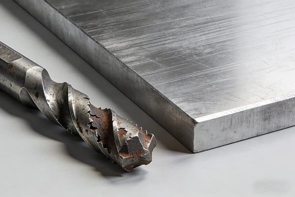
This is the most common type of wear.2 Imagine tiny, hard particles in the workpiece material acting like sandpaper, slowly grinding away at the cutting edge. This happens with materials that contain hard carbides or abrasive inclusions.3 It shows up as a uniform rounding of the cutting edge, called flank wear.
2. Adhesive Wear (The Sticking and Tearing)
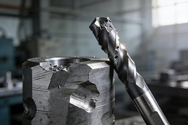
Under intense pressure and heat, bits of the workpiece can literally weld themselves onto the tool's surface. This is called a built-up edge (BUE).%20Introduction%20to%20Manufacturing%20Processes%20.pdf&stafftype=staffcourses)4 When this BUE breaks off, it often tears away a small piece of the carbide tool with it, causing chipping and a rough surface finish.
3. Diffusion Wear (The Chemical Breakdown)
This is the silent killer at high speeds. When the tool gets extremely hot, atoms from the carbide tool can "diffuse" or migrate into the workpiece material5. This chemically changes and weakens the tool's cutting edge, causing it to wear down very quickly, often leaving a crater on the rake face.
| Wear Type | What It Looks Like | Main Cause |
|---|---|---|
| Abrasive | A smooth, rounded cutting edge | Hard particles in the material |
| Adhesive | Material stuck to the tool, chipping | High pressure, low speeds |
| Diffusion | A crater behind the cutting edge | Extreme heat from high speeds |
Am I Starting with the Right Tool for the Job? (The Foundation of Wear Resistance)?
You grab a general-purpose end mill for a tough, high-hardness material. It fails almost immediately, costing you time, money, and a lot of frustration.
Your tool's base material and coating are your first line of defense against wear. Using a tool specifically designed for your workpiece material is the single most important factor for long life.
You can't win a fight with the wrong equipment. I've seen shops try to save a few dollars on a standard end mill only to burn through five of them on a job that one high-performance tool could have handled easily. The foundation of wear resistance is built into the tool itself, long before it ever touches metal.
Start with a Better Substrate: Ultrafine Particle Carbide
The basic ingredient of our end mills is tungsten carbide. The wear resistance of this carbide depends on how fine the grain particles are.6 Think of it like sand. Fine sand packs together much tighter and harder than coarse gravel. It's the same with carbide. Our ultrafine particle substrates have a stronger bond, making them much more resistant to abrasive wear. For any material over HRC50, like mold steels, this should be your starting point. Some of our premium tools also include elements like Tantalum Carbide (TaC) to improve high-temperature hardness and fight diffusion wear7 during high-speed cutting.
When to Upgrade: CBN and PCD
For the toughest jobs, you need to move beyond carbide.
- Cubic Boron Nitride (CBN): This is the second hardest material known, right after diamond.8 We recommend CBN tools for milling hardened steels and high-temperature superalloys. The wear resistance is incredible.
- Polycrystalline Diamond (PCD): For non-ferrous materials, especially high-silicon aluminum or abrasive composites like carbon fiber, nothing beats diamond. PCD tools offer exceptional life and finish in these specific applications.9
Are My Cutting Parameters Optimized, or Just 'Good Enough'?
You use the same generic speeds and feeds from a chart for every job. But your tools are still wearing out, and you don't know why.
"Good enough" parameters are a primary cause of premature wear. Small, targeted adjustments to your speed, feed, and depth of cut can double your tool life by reducing heat and stress.
Many machinists I work with are so focused on cycle time that they push their tools to the absolute limit. But sometimes, going a little slower actually saves time and money by preventing tool changes. Your cutting parameters control the two biggest enemies of an end mill: heat and stress.
Speed (RPM): The Heat Generator
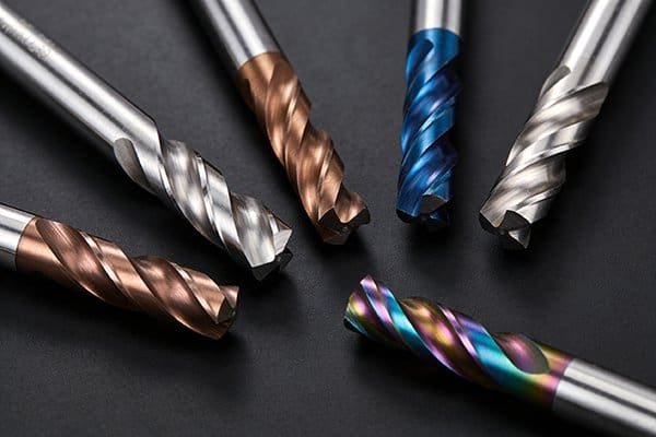
Cutting speed is the biggest factor in generating heat.10 Running too fast creates excessive heat at the cutting edge, which softens the tool material and rapidly accelerates diffusion wear. It can also cause the tool's coating to break down and fail. While advanced coatings like AlTiN are designed to handle high heat, there's always a thermal limit. If you see the corners of your tool breaking down quickly, your first move should be to reduce the RPM by 10-15%.
Feed Rate (mm/min): The Chip Load
The feed rate determines your chip thickness. This is a balancing act. If your feed is too low, the tool doesn't cut cleanly; it rubs against the material. This rubbing action creates friction and heat, leading to rapid abrasive wear.11 If your feed is too high, you put too much pressure on the cutting edge, which can cause it to chip or break completely. You need to find the sweet spot where you are forming a proper chip, which efficiently carries heat away from both the tool and the part12.
Is My Machining Environment Helping or Hurting My Tool?
You have the perfect tool and the right parameters, but the end mill still fails. This is incredibly frustrating, and the cause is often hidden in your setup.
Your tool holder, machine rigidity, and coolant strategy can make or break your tool's performance. Vibration and poor chip evacuation are silent killers that cause unpredictable and rapid wear.
The tool itself is only one part of the equation. Everything around it has a massive impact on its life. I always tell my customers to think of the entire system, from the spindle to the workpiece. A weak link anywhere in that chain will put all the stress on the most fragile part: the cutting edge of your end mill.
Rigidity is King: Tool Holders and Machine Health
Any vibration in the setup acts like a tiny hammer, constantly pounding on the cutting edge. This leads to micro-chipping, which dulls the edge and leads to total failure. Where does this vibration come from?
- Poor Tool Holding: Using an old, worn-out collet or a low-quality tool holder is a common mistake. A high-quality, balanced holder provides a rigid grip and reduces runout.
- Long Tool Overhang: The further the tool sticks out from the holder, the more it will vibrate. Always use the shortest tool possible for the job.
- Machine Condition: Worn spindle bearings or loose machine ways can also introduce harmful vibrations.
Coolant and Chip Evacuation
The primary jobs of coolant are to reduce heat and flush chips out of the way. If chips are not cleared effectively, the tool will re-cut them. This is a major cause of abrasive wear and sudden tool breakage. Ensure your coolant nozzles are aimed directly at the cutting zone. In some cases, especially with coatings designed to run hot, a strong blast of compressed air can be more effective for chip evacuation and avoids the thermal shock of coolant hitting a hot tool.
Can I Get a Quick Diagnostic Chart to Pinpoint My Wear Problem?
You're looking at a worn tool, but it's hard to know what the wear pattern is telling you. You need a simple way to connect the problem to a solution.
Yes. This quick diagnostic chart links the most common types of visual wear to their likely cause and the first solution you should try. It's a practical starting point for troubleshooting.
Over the years, I've learned that a worn tool tells a story. You just have to know how to read it. I put together this simple table based on the problems we see most often. Find the wear pattern on your tool that looks most like the description, and it will point you toward the most likely root cause and a solution you can try right away. This turns troubleshooting from a guessing game into a logical process.
End Mill Wear Diagnostic Chart
| Type of Wear (What You See) | Likely Cause | First Thing to Check |
|---|---|---|
| Uniform Flank Wear (A smooth, even rounding of the cutting edge) | Abrasive Wear. The tool material is not hard enough for the workpiece. Cutting speed may also be too high, generating friction. | Reduce Cutting Speed (RPM) by 15%. If that doesn't help, you need a tool with a more wear-resistant substrate (like ultrafine carbide) or coating. |
| Chipping (Small, random nicks and flakes on the cutting edge) | Instability or Rubbing. This is often caused by vibration from poor tool holding, a long overhang, or a feed rate that is too low. | Increase Feed Rate by 10-15%. Also, check your tool holder for runout and use the shortest tool possible to maximize rigidity. |
| Cratering (A scoop or dish-shaped hole on the top face of the tool) | Diffusion Wear. Extreme heat is causing a chemical reaction between the tool and the workpiece chips. | Use a Coated Tool. A heat-resistant coating like AlTiN provides a thermal barrier. If already coated, reduce your cutting speed to lower the heat. |
| Built-Up Edge (BUE) (Workpiece material is welded onto the cutting edge) | Adhesive Wear. This is common in gummy materials like aluminum or some stainless steels, especially at lower cutting speeds. | Increase Cutting Speed (RPM). Higher speeds can reduce the tendency for material to stick. A self-lubricating coating (like DLC for aluminum) also helps significantly. |
Conclusion
Solving end mill wear isn't about one magic fix. It’s a systematic process of matching your tool to the job, optimizing parameters, and ensuring a stable machining environment.
"Tool wear mechanisms during machining: Its related problems and ...", https://ui.adsabs.harvard.edu/abs/2025AIPC.3263p0078O/abstract. A machining-materials reference classifies abrasive, adhesive, and diffusion mechanisms among the principal wear processes affecting cutting tools during metal cutting. Evidence role: definition; source type: education. Supports: The three main culprits of tool wear are abrasion, adhesion, and diffusion.. Scope note: The source may discuss cutting tools broadly rather than end mills specifically. ↩
"Tool wear analysis in various machining processes and study of ...", https://d.lib.msu.edu/etd/1409. A peer-reviewed review or machining textbook can support that abrasive flank wear is commonly observed in cutting operations, although prevalence varies by workpiece material, tool material, and cutting conditions. Evidence role: expert_consensus; source type: paper. Supports: Abrasive wear is the most common type of end mill wear.. Scope note: The statement is context-dependent and may not be universally true for every machining process or material pair. ↩
"[PDF] Performance of laser surface textured cemented carbide tools during ...", https://upcommons.upc.edu/bitstreams/405fef2a-c2b9-4349-84e4-9e07ae7d6105/download. Materials and machining literature describes abrasive tool wear as resulting from hard phases or inclusions in the workpiece sliding against the cutting edge. Evidence role: mechanism; source type: paper. Supports: Abrasive wear occurs when hard carbides or abrasive inclusions in the workpiece grind the cutting edge.. Scope note: Support is mechanistic and does not quantify the wear rate for a particular workpiece alloy. ↩
"[PDF] Manufacturing Processes(IM 212)", https://aast.edu/pheed/staffadminview/pdf_retreive.php?url=67_31085_IM212_2017_1__1_1_01)%20Introduction%20to%20Manufacturing%20Processes%20.pdf&stafftype=staffcourses. Manufacturing engineering references define built-up edge as workpiece material adhering or welding to the cutting tool under suitable temperature and pressure conditions. Evidence role: definition; source type: education. Supports: Built-up edge is workpiece material adhering or welding to the tool surface during cutting.. Scope note: The definition applies broadly to metal cutting and is not limited to carbide end mills. ↩
"Analysis of the effect of crystal evolution on tool diffusion wear based ...", https://pmc.ncbi.nlm.nih.gov/articles/PMC11909158/. Cutting-tool wear literature explains diffusion wear as atomic transfer between tool and workpiece or chip at elevated cutting temperatures. Evidence role: mechanism; source type: paper. Supports: At high cutting temperatures, atoms from a carbide tool can diffuse into the workpiece or chip, contributing to tool wear.. Scope note: The source may describe diffusion between tool and chip rather than specifically into the bulk workpiece. ↩
"[PDF] Advanced characterization techniques in cemented carbides", https://upcommons.upc.edu/bitstreams/757ac7e7-6c0a-4ca2-bcbe-e9a31484a18f/download. Research on cemented carbide tools reports that carbide grain size influences hardness, toughness, and wear resistance, with finer-grained carbides often improving resistance to abrasive wear. Evidence role: mechanism; source type: paper. Supports: Tungsten carbide wear resistance depends in part on carbide grain size.. Scope note: The relationship can depend on cobalt binder content, sintering, and the balance between hardness and toughness. ↩
"Investigation on diffusion wear during high-speed machining Ti-6Al ...", https://hero.epa.gov/reference/4792415/. Studies of cemented carbides note that tantalum carbide additions can improve high-temperature properties and affect diffusion or crater-wear resistance in cutting applications. Evidence role: mechanism; source type: paper. Supports: Tantalum carbide additions can improve high-temperature hardness and help resist diffusion-related wear.. Scope note: The effect depends on carbide composition and cutting conditions; a general source may not validate a specific manufacturer's formulation. ↩
"Boron nitride - Wikipedia", https://en.wikipedia.org/wiki/Boron_nitride. Reference sources identify cubic boron nitride as one of the hardest known materials and commonly rank it below diamond in hardness. Evidence role: definition; source type: encyclopedia. Supports: Cubic boron nitride is generally considered the second-hardest material after diamond.. Scope note: Hardness rankings can vary by measurement method and material form. ↩
"(PDF) Composite Machining Guide A34 Composite Machining", https://www.academia.edu/40106625/Composite_Machining_Guide_A34_Composite_Machining. Machining studies report that polycrystalline diamond tooling provides high wear resistance and good surface finish when cutting non-ferrous and abrasive composite materials such as high-silicon aluminum or CFRP. Evidence role: general_support; source type: paper. Supports: PCD tools can provide long tool life and good finish in non-ferrous and abrasive composite machining.. Scope note: The evidence supports the application class generally and does not guarantee performance for every grade, tool geometry, or machining setup. ↩
"[PDF] 3D Modeling of Temperature by Finite Element in Machining with ...", https://flyingv.ucsd.edu/mostafa/papers/WASET_14141.pdf. Metal-cutting research and manufacturing texts show that cutting speed strongly influences cutting temperature and tool wear because heat generation rises with cutting velocity. Evidence role: mechanism; source type: education. Supports: Cutting speed is a major factor in heat generation during machining.. Scope note: Calling it the “biggest” factor may vary with feed, depth of cut, tool geometry, and material; the source should support strong influence rather than absolute dominance in all cases. ↩
"[PDF] Helical - MACHINING GUIDEBOOK", https://web.mae.ufl.edu/designlab/Advanced%20Manufacturing/Helical_Machining_Guidebook.pdf. Machining references explain that insufficient chip load can cause rubbing or ploughing rather than effective cutting, increasing frictional heat and accelerating tool wear. Evidence role: mechanism; source type: education. Supports: Too low a feed or chip load can cause rubbing, frictional heat, and accelerated tool wear.. Scope note: The exact transition from cutting to rubbing depends on edge radius, workpiece material, and tool geometry. ↩
"A Case Study of Hard Milling of SKD 61 Steel - Academia.edu", https://www.academia.edu/69621310/Minimization_of_Temperature_in_Cutting_Zone_A_Case_Study_of_Hard_Milling_of_SKD_61_Steel. Metal-cutting heat-transfer analyses describe the chip as a major path for removing heat from the cutting zone, though the fraction of heat carried by the chip varies with material and cutting parameters. Evidence role: mechanism; source type: paper. Supports: Proper chip formation helps carry heat away from the cutting zone.. Scope note: The source supports the heat-removal mechanism generally, not a specific end mill operation or percentage for this article’s examples. ↩