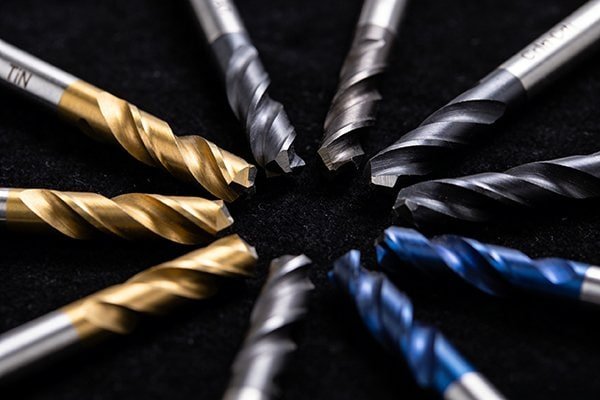
Ever wonder how a spinning tool precisely carves solid steel? Choosing the wrong one is costly and can ruin your workpiece. This guide explains exactly how end mills work.
An end mill is a rotary cutting tool that carves metal using sharp edges on its sides and tip.1 Unlike a drill, it can cut sideways (laterally), allowing it to create slots, pockets, contoured surfaces, and complex profiles in a workpiece.2
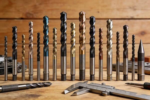
When I first started in our shop over a decade ago, the sheer variety of end mills was overwhelming. They all looked like fancy drill bits to me. But once someone explained the basic mechanics, everything clicked into place. Understanding how they work is the first step to making great parts, and it’s not as complicated as it looks. Let's break it down together, and you'll see how you can select the right tool for your job every time, saving you time and money.
First, What Is Actually Happening During an End Milling Cut?
The process seems like magic, a blur of motion and flying chips. Not knowing what is happening can lead to chatter, poor finish, or broken tools. Let's demystify it.
During a cut, the end mill's rotating helical edges, called flutes, shear off small pieces of the workpiece.3 These pieces are called "chips." The shape of the flutes is designed to evacuate these chips away from the cutting zone, preventing heat buildup.4
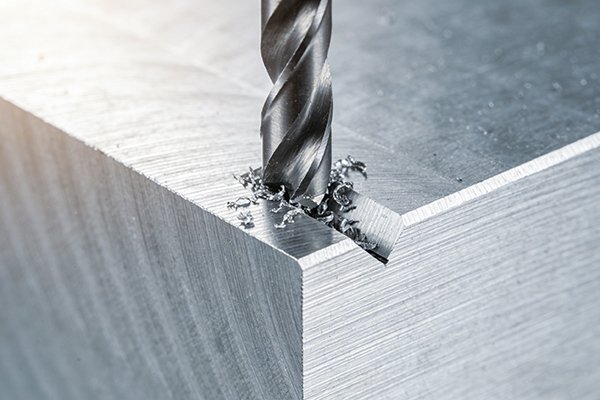
Let's dive deeper into this process. The magic is all in the geometry. An end mill is designed to cut in two primary ways, which is what makes it so versatile.
Side Milling vs. Bottom Milling
- Side Milling (Peripheral Milling): This is when you use the cutting edges along the side of the end mill to cut a vertical or contoured wall. Think of shaping the outside profile of a part. The helix angle of the flutes plays a big role here, as it helps pull the chips up and away from the wall you are cutting, ensuring a clean surface.5
- Bottom Milling (Face/Slot Milling): This uses the cutting edges on the very tip, or end, of the tool. It's used for creating flat-bottomed pockets, slots, or facing a surface to make it perfectly flat. For this to work, the end mill must be "center-cutting," meaning its cutting edges go all the way to the center of the tool's tip.6
In both cases, success depends on forming and clearing a good chip. If chips get clogged in the flutes, they will overheat, weld to the tool or part, and cause the tool to break.7 That's why the number of flutes and their shape is so important.
Isn't an End Mill Just a Fancy Drill Bit? (The Key Differences)
To a beginner, an end mill and a drill bit can look very similar. But if you try to use a drill bit for milling, it will snap almost instantly. Why?
No, they are fundamentally different tools. A drill bit is designed only for plunging straight down (axial cutting) to create a hole.8 An end mill has strong cutting edges on its sides, allowing it to move sideways (radial cutting) to carve out features.
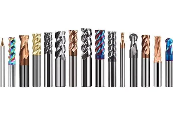
I see this confusion all the time with new machine operators. The mistake is understandable, but it's a critical distinction. The strength and design purpose are completely different. A drill bit's force is directed straight down its axis. An end mill is built to withstand massive side-loading forces as it carves through material laterally.9 Using one for the other's job is a recipe for failure. Let's look at a clear breakdown.
Key Functional Differences
Here is a simple table that shows the main differences in their design and application.
| Feature | Drill Bit | End Mill |
|---|---|---|
| Primary Motion | Axial (plunging) only | Radial (sideways) and Axial |
| Cutting Edges | Only on the tip (point) | On the tip and along the sides (flutes) |
| Main Purpose | Creating round holes | Creating slots, pockets, profiles, surfaces |
| Shank Strength | Designed for axial force | Designed for strong radial (side) force |
While some end mills are "center-cutting" and can plunge like a drill bit to start a pocket, their primary job begins once they start moving sideways. A standard drill bit has no ability to cut sideways. Its body is not designed for it, and it has no cutting edges there. Trying to do so will overload and break it immediately.
So, What Kinds of Shapes and Features Can I Actually Make with It?
You have the right tool, you know it's not a drill bit. But what can you actually do with it? You're limited only by your machine and your imagination, not the tool.
With the right end mills, you can create almost any shape.10 This includes flat-bottomed pockets, vertical walls, open slots, angled chamfers, rounded edges, complex 3D-curved surfaces, and even threads. The tool's tip shape dictates the final geometry.
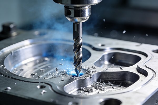
At our factory, we use end mills to produce an incredible range of features for our clients in the automotive, aerospace, and mold-making industries. A single metal block can be transformed into a complex part using a sequence of different end mill operations. It's all about matching the tool to the desired feature.
Common Machined Features
Here are some of the most common shapes you can create:
-
### Flat Pockets, Slots, and Shoulders A standard flat-bottom end mill is your workhorse for creating any feature with a flat floor and 90-degree walls. This is fundamental for most mechanical parts.
-
### 3D Contours and Surfaces For complex, organic shapes like those found in molds or aerospace components, you need a ball end mill.11 Its perfectly round tip can move in three dimensions to create smooth, flowing surfaces without sharp corners.
-
### Rounded Edges If you need a specific radius on an inside corner where a floor meets a wall, you use a corner radius end mill (also called a bull nose). This adds strength to the part and is a very common requirement.12
-
### Angled Edges and Chamfers A chamfer mill is used to create a clean, angled edge on a part, which is great for deburring, lead-ins for holes, or just for aesthetics.
-
### Threads Yes, you can even make threads! A thread mill is a specialized end mill that moves in a helical path to cut internal or external threads. This gives you more control than using a traditional tap.
Do I Need a Different Type of End Mill for Every Single Shape?
Seeing that long list of shapes can be intimidating. Does this mean your workshop needs hundreds of different tools? Buying every type is expensive and often unnecessary for most shops.
No, you don't need a unique tool for every feature. A small set of core end mills—like a flat, a ball, and a corner radius—can handle the vast majority of jobs. The key is understanding how geometry, flutes, and coating work together.
When we consult with a new machine shop, we don't recommend they buy our entire catalog. We help them start with a versatile "starter pack." You can do so much with just a few key types. The secret is not in having every tool, but in deeply understanding the few you have. Let's break down the main variables you'll choose from.
By Shape: The "Business End"
This is the most obvious difference. The shape of the tip defines the shape you cut.
- Flat: For 2D features like pockets and slots.
- Ball: For 3D contouring and surfacing.
- Corner Radius (Bull Nose): For creating a specific radius at the bottom of a wall.
By Flutes: How Many Teeth?
The number of flutes affects your feed rate and chip evacuation.
- 2-Flute: Excellent chip clearance. The top choice for aluminum and other non-ferrous metals that produce large, gummy chips.
- 3-Flute: A great general-purpose option that bridges the gap. Good for slotting and profiling in steels.
- 4-Flute and More: More cutting edges mean a smoother finish and higher feed rates. Best for finishing operations and milling harder materials like steel and stainless steel. The smaller chip gullets make them less ideal for deep slotting.
By Coating: The Armor
The coating is a micro-thin layer that protects the tool and improves performance.
- Uncoated: Best for aluminum, as some coatings can react with it.
- TiN (Titanium Nitride): A basic, all-purpose coating that increases hardness and wear resistance.
- TiAlN (Titanium Aluminum Nitride): Our most popular coating. The aluminum provides excellent heat resistance, making it perfect for high-speed machining of steel, stainless steel, and cast iron.
Can You Give Me a Quick Visual Chart to Identify Them All?
Remembering all these types is hard when you're just starting out. Grabbing the wrong tool from the drawer can scrap an expensive piece of material. So let's make it simple.
Of course. Here is a simple reference chart that organizes common end mills by their shape and primary job. Use this as a quick guide next to your machine to help you grab the right tool and build your confidence.
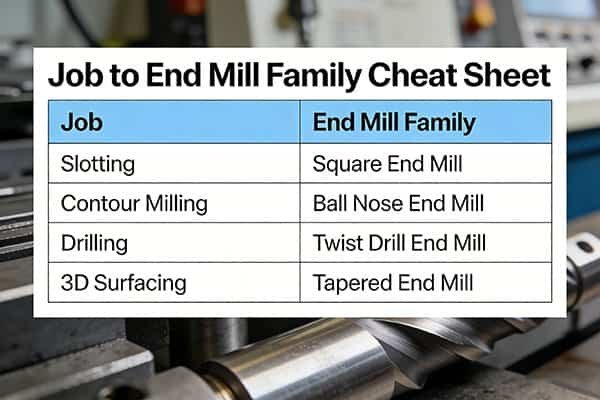
Think of this table as your cheat sheet. When we train new staff, we have a similar chart posted in the tool crib. It helps everyone speak the same language and reduces errors. A quick glance can save you a lot of headaches.
Quick Identification Guide
| Tool Type | Visual Profile | Primary Use | Best For Materials |
|---|---|---|---|
| Flat End Mill | Flat Tip, Sharp Corner | Pockets, Slots, Profiling (2D) | All Materials |
| Ball End Mill | Fully Rounded Tip | 3D Contouring, Surfacing | All Materials |
| Corner Radius Mill | Flat Tip, Rounded Corners | Stronger corners, reducing stress | Hardened Steels, Alloys |
| 2-Flute End Mill | Two large flute valleys | Aggressive slotting, roughing | Aluminum, Plastics, Wood |
| 4-Flute End Mill | Four smaller flute valleys | Finishing, profiling, shallow slots | Steels, Stainless, Cast Iron |
| TiAlN Coated | Purple-black/Dark Gray | High-speed, high-heat machining | Steels, Stainless, Ti Alloys |
| Uncoated (Bright) | Shiny Silver Finish | Prevents chip welding | Aluminum, Brass, Copper |
This table doesn't cover every single specialty tool, like the thread mills or tapered end mills we mentioned. However, these seven categories represent over 90% of the work done in most machine shops. Master these, and you are well on your way to becoming an expert.
Conclusion
Choosing the right end mill is key to great results. Start with the basics, understand how the shape, flutes, and coating work, and your machining will improve dramatically.
"Module 13 :: Milling - GFJC Archive of Projects", https://archive.gfjc.fiu.edu/firearms/module13/fir_m13_t04_01_b.htm. A manufacturing-process reference defines an end mill as a rotating multi-edge milling cutter with cutting edges on the end face and periphery, supporting the article’s basic definition of the tool. Evidence role: definition; source type: education. Supports: An end mill is a rotary cutting tool with cutting edges on both its end and sides.. ↩
"IFL Training Shift 05-1: Drill/Mill - University of Maryland", https://dozuki.umd.edu/Guide/IFL+Training+Shift+05-1:+Drill-Mill/645. A machining handbook or university manufacturing note explains that milling cutters remove material by peripheral and face cutting motions, whereas twist drills are primarily designed for axial hole-making; this supports the functional contrast but does not prove every possible feature geometry. Evidence role: definition; source type: education. Supports: End mills can cut laterally and create slots, pockets, contours, and profiles, unlike standard drills that are primarily axial hole-making tools.. Scope note: Contextual support for the difference between drilling and milling; specific feature capability depends on machine setup, cutter geometry, and programming. ↩
"[PDF] A Review of Wood Machining Literature with a Special Focus on ...", https://bioresources.cnr.ncsu.edu/wp-content/uploads/2016/06/BioRes_08_2_3122_Naylor_Hackney_Review_Wood_Machining_Focus_Sawing_3847.pdf. A metal-cutting mechanics source describes milling as chip formation by shearing as rotating cutter teeth engage the workpiece, supporting the explanation of how end-mill flutes remove material. Evidence role: mechanism; source type: education. Supports: End-mill flutes shear material from the workpiece as chips during cutting.. ↩
"The Ultimate Guide to Sharpening End Mills: Expert Tips & Techniques", https://imba.missouri.edu/how-to-sharpen-end-mills-1518085664.html. A machining reference explains that flute geometry provides chip space and chip evacuation in milling, reducing recutting and heat accumulation; this supports the mechanism, though actual heat levels also depend on speed, feed, coolant, and material. Evidence role: mechanism; source type: education. Supports: End-mill flute geometry helps evacuate chips from the cutting zone and can reduce heat-related cutting problems.. Scope note: Support is general because chip evacuation performance varies with cutting parameters and workpiece material. ↩
"[PDF] Helical - MACHINING GUIDEBOOK", https://web.mae.ufl.edu/designlab/Advanced%20Manufacturing/Helical_Machining_Guidebook.pdf. A machining text or research paper on end-mill geometry describes helix angle as influencing chip flow, cutting forces, and surface finish, supporting the article’s statement about chip removal and surface quality in peripheral milling. Evidence role: mechanism; source type: paper. Supports: End-mill helix angle affects chip evacuation and surface finish during side milling.. Scope note: The source would support the general influence of helix angle; it may not guarantee a clean surface under all machining conditions. ↩
"Feeds and Speed Calculator - Plunge Rate - MIT", https://pub.pages.cba.mit.edu/feed_speeds/parameter_explanations/plungerate.html. A machining handbook distinguishes center-cutting end mills, whose end teeth reach the tool centerline, from non-center-cutting end mills, supporting the requirement for plunging and pocket-starting operations. Evidence role: definition; source type: education. Supports: Center-cutting end mills have cutting edges extending to the center of the tool tip and are required for plunging into material.. Scope note: This supports plunging capability; bottom milling after entry can also involve toolpaths that do not require direct plunging. ↩
"Effect of Built-Up Edge Formation during Stable State of Wear ...", https://pmc.ncbi.nlm.nih.gov/articles/PMC5706177/. A machining or tribology source describes chip clogging and recutting as causes of increased temperature, built-up edge or chip welding, and tool failure, supporting the article’s failure mechanism. Evidence role: mechanism; source type: paper. Supports: Chip clogging in end-mill flutes can increase heat, promote chip welding or built-up edge, and contribute to tool breakage.. Scope note: The cited source may describe these as common risks rather than inevitable outcomes in every cut. ↩
"[PDF] STABILITY ANALYSIS WITH UNCERTAINTY FOR TWIST DRILLING", https://mtrc.utk.edu/wp-content/uploads/sites/45/2020/10/drilling-ASPE.pdf. A manufacturing-process reference describes twist drilling as an axial hole-making operation using a rotating drill fed along its axis, supporting the article’s distinction between drilling and milling. Evidence role: definition; source type: education. Supports: A conventional drill bit is primarily designed for axial plunging to create holes.. Scope note: Some specialized drills and machining strategies may have limited nonstandard uses, but the statement is accurate for conventional twist drills. ↩
"[PDF] Cutting force and stability prediction for inserted cutters", https://mtrc.utk.edu/wp-content/uploads/sites/45/2020/09/cutting-force-and-stability-for-inserted-cutters.pdf. A milling-process source explains that end mills are used in peripheral and profile milling where radial cutting forces act on the cutter, supporting the claim that end mills are designed for lateral loads. Evidence role: mechanism; source type: education. Supports: End mills are designed for milling operations that impose radial or lateral cutting forces.. Scope note: The adjective “massive” is qualitative; neutral sources will usually discuss radial or lateral cutting forces rather than use that wording. ↩
"[PDF] Development of a postprocessor for a multi-axis CNC milling center", https://scholarsmine.mst.edu/cgi/viewcontent.cgi?article=8096&context=masters_theses. A CNC machining or manufacturing reference describes milling as capable of producing slots, pockets, profiles, freeform surfaces, and other complex geometries when paired with appropriate cutters and machine motion, supporting the broad versatility claim in context. Evidence role: general_support; source type: education. Supports: End mills, when used with suitable CNC toolpaths and cutter geometries, can produce a wide range of part shapes and features.. Scope note: This is contextual support; “almost any shape” is an overstatement limited by tool access, machine axes, fixturing, tolerances, and material constraints. ↩
"[PDF] STL-based Finish Machining of Rapid Manufactured Parts and Tools", https://repositories.lib.utexas.edu/bitstreams/e48fd4f8-3411-4e26-991a-f60fcc2cccd1/download. A manufacturing or CAM reference explains that ball-nose end mills are commonly used for 3D contouring and freeform surface finishing because the spherical tip can machine smooth curved surfaces, supporting this tool-selection claim. Evidence role: mechanism; source type: education. Supports: Ball end mills are commonly used to machine complex 3D contoured surfaces such as molds and aerospace-style freeform geometry.. Scope note: “Need” is context-dependent; other cutters may be used for some curved surfaces, but ball-nose tools are a standard choice for 3D contour finishing. ↩
"[PDF] 2-4: Stress Concentration Caused by Sudden Change in Form - NJIT", https://web.njit.edu/~sengupta/met%20301/Stress%20Concentration.pdf. A mechanics-of-materials reference explains that sharp internal corners create stress concentrations and that increasing fillet radius reduces stress concentration factors, supporting the rationale for rounded internal corners. Evidence role: mechanism; source type: education. Supports: Adding a radius to an internal corner can reduce stress concentration and improve part strength.. Scope note: The source supports stress-reduction mechanics; whether a corner-radius end mill is the chosen manufacturing method depends on design requirements and process planning. ↩