
Drilling cast iron feels slow and chews through your tools. This costs you valuable machine time and money. A specialized drill designed for high feed rates can completely change your results.
The Kennametal HPR drill dominates cast iron by using a unique asymmetrical point geometry designed for extremely high feed rates. This design breaks up harmful vibrations and provides stability, allowing for 2-5 times the productivity of standard drills while maintaining excellent hole quality.
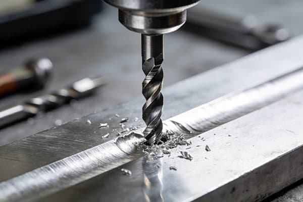
I've spent years in machine shops, and I've seen countless drills fail in cast iron. It seems simple to machine, but it has a nasty habit of wearing tools down surprisingly fast. When we first tested drills like the Kennametal HPR, the results were shocking. The machine sounded different, the chips flew off differently, and the cycle time dropped dramatically. It forced us to rethink our entire approach to drilling. Understanding why this drill works so well is key to unlocking massive productivity gains, especially if you're dealing with high-volume production. Let's break down what makes this tool a game-changer for cast iron.
What makes cast iron so abrasive to drill?
You think cast iron is easy to machine, but your drills keep wearing out. These constant tool changes are destroying your shop's productivity and profitability. The solution is understanding the material itself.
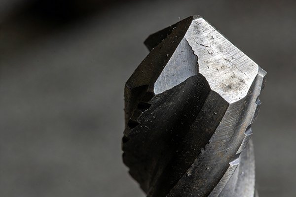
Cast iron is abrasive because it contains free graphite particles that act like sandpaper on a drill's cutting edge.1 It can also have hard spots, like cementite or sand inclusions from casting, which cause chipping and rapid wear on standard tools.2
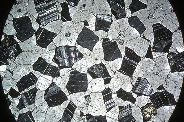
When we talk about cast iron, we are not talking about just one material. There are many types, and each behaves differently under the drill.3 The most common is grey cast iron, which is full of graphite flakes.4 These flakes make chips break off easily, but they are also very abrasive. Imagine rubbing your tool against fine-grit sandpaper with every rotation. That's what's happening. Ductile iron is tougher and has rounded graphite nodules, which puts more pressure on the drill point.5
The problems don't stop there. Depending on the cooling process, you can get hard spots in the material. These are areas of iron carbide, or cementite, which are extremely hard.6 Hitting one of these is like hitting a tiny rock. A standard drill bit can chip instantly. You also have to worry about leftover sand from the casting mold. This sand is silica, and it's incredibly abrasive.7
| Material Feature | Effect on Drilling | Tool Wear Type |
|---|---|---|
| Graphite Flakes | Acts as a dry lubricant but is highly abrasive. | Flank Wear |
| Hard Spots (Cementite) | Creates shock load on the cutting edge. | Chipping, Fracture |
| Sand Inclusions | Extremely abrasive, like grinding the tool. | Severe Abrasive Wear |
| Pearlitic Matrix | Harder and stronger structure than ferrite. | Increased Force & Heat |
Understanding these factors is the first step. You are not just drilling metal; you are fighting a combination of abrasive particles and hard inclusions.
How does the HPR's point geometry conquer cast iron?
Your standard drills vibrate and chip when you push them in cast iron. This leads to out-of-spec holes, broken tools, and frustrating downtime. The secret to stability and speed is in the drill's design.
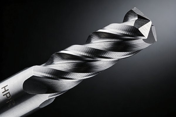
The HPR drill's asymmetrical point geometry breaks the symmetrical vibration pattern of standard drills.8 This unique design distributes cutting forces unevenly, which provides incredible stability and allows the drill to handle extremely high feed forces without wavering or breaking.
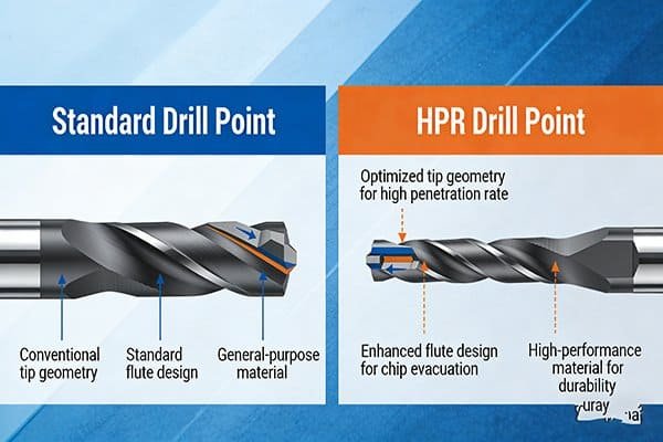
A regular drill is perfectly symmetrical. When you push it hard, it wants to vibrate in a predictable, balanced pattern. This vibration is what limits how fast you can feed the drill. The HPR drill flips this idea on its head. Its cutting edges are not symmetrical. I like to explain it like this: a regular drill is like trying to force a perfectly round stick into a board. Push too hard, and it wobbles. The HPR drill is like a specially designed impact tool with an offset handle; its strange shape is precisely why it can handle enormous force without losing stability.
This design has a few key parts:
- Asymmetrical Cutting Edges: They distribute cutting force and heat to different areas. This prevents the drill from chattering and allows it to withstand much higher feed pressure.9
- Self-Centering Chisel Edge: The very tip of the drill is specially sharpened. It bites into the material instantly and centers itself, which prevents the "walking" you see with other drills. This ensures a smooth start even at high feed rates.
- Reinforced Flutes: The grooves on the drill are wider and stronger to handle the huge volume of chips created by high-feed drilling. This prevents chips from packing up and breaking the tool.
| Feature | Standard Drill | Kennametal HPR Drill | Advantage |
|---|---|---|---|
| Symmetry | Symmetrical | Asymmetrical | Breaks harmonic vibration, increases stability. |
| Chisel Edge | Standard | Sharp, Self-Centering | Prevents "walking," reduces entry force. |
| Force Distribution | Evenly Balanced | Unevenly Distributed | Allows for much higher feed pressure. |
This geometry is the mechanical foundation that allows the HPR drill to achieve its incredible performance.
Are you running your HPR drill fast enough?
You bought expensive HPR drills but are not seeing the huge productivity gains you expected. You are likely wasting the tool's true potential and your money. The secret is not speed, but feed.
You are probably not running your HPR drill with enough feed. These drills are designed for a very high feed per revolution (fn), often 2-5 times higher than standard drills.10 Using conventional feed rates underutilizes their core strength and can cause premature wear.
Most of us are trained to increase the spindle speed (RPM) to improve cycle times. With HPR drills, you have to change your thinking. The main goal is to maximize the feed per revolution (fn).11 While the cutting speed (Vc) should be reasonable, the real magic happens when you push the drill forward aggressively with each turn. Running it with a low feed is like trying to use a sledgehammer to tap in a nail. You are not using the tool's designed strength.
This high-feed approach works because it gets the cutting edge in and out of the material very quickly. It distributes the cutting load across a larger part of the cutting edge instead of concentrating heat and pressure on one small spot. This leads to a better metal removal rate (MRR) and, surprisingly, can even improve tool life in some cases. The goal is to make a clean, thick chip and get the drill out of the hole as fast as possible.
| Parameter | 10mm Standard Drill | 10mm HPR Drill | The Difference |
|---|---|---|---|
| Cutting Speed (Vc) | 100 m/min | 120 m/min | ~20% Faster |
| Spindle Speed (RPM) | ~3180 RPM | ~3820 RPM | |
| Feed per Rev (fn) | 0.20 mm/rev | 0.65 mm/rev | +225% Higher |
| Feed Rate (Vf) | 636 mm/min | 2483 mm/min | ~4x Faster |
Look at the table. The feed rate is where the huge difference is. If you are not pushing the feed rate, you are leaving most of the HPR drill's performance on the table.
What do the wear patterns on your HPR drill reveal?
Your HPR drill is wearing out, but you have no idea why. Just replacing the tool without understanding the cause means you are throwing money away and will repeat the same mistake. The drill itself is telling you what's wrong.
Reading the wear on your HPR drill is critical for optimization. Uniform wear on the flank is good. However, if you see chipping on the cutting edge, your feed may be too high or the setup is unstable. Excessive crater wear indicates your speed is too high.12
Every worn drill tells a story. Learning to read that story is how you become a great machinist and save your company money. With a high-performance tool like the HPR, small adjustments based on wear patterns can lead to big improvements in tool life and part quality. Don't just throw the dull drill in the bin. Take 30 seconds to look at it under a light. Is the wear even? Are there chips? Is material stuck to the edge? Answering these questions helps you fine-tune your process instead of just guessing. Here is a simple guide I use to diagnose problems on the shop floor.
| Wear Pattern | What It Looks Like | Probable Cause | How to Fix It |
|---|---|---|---|
| Uniform Flank Wear | A consistent, even band of wear along the cutting edge. | Normal operation. | This is the goal! Replace the tool. |
| Chipping | Small pieces broken off the cutting edge. | Feed is too high; unstable setup; hard spots. | Reduce feed; check tool holder and workpiece clamping. |
| Crater Wear | A scoop or crater on the tool face behind the edge. | Cutting speed is too high; too much heat. | Reduce cutting speed (Vc); improve coolant flow. |
| Built-Up Edge (BUE) | Material welded onto the cutting edge. | Cutting speed is too low; poor chip flow. | Increase cutting speed; use coated tool; check coolant. |
By paying attention to these signs, you can adjust your parameters to find the perfect balance. This will maximize the life of your expensive HPR drills and ensure you are getting every bit of performance out of them.
When should you choose HPR over a general-purpose drill?
You are not sure if the high price of an HPR drill is really worth it. Choosing the wrong drill for the job wastes money, either on an expensive tool you don't need or on lost machine time.
You should choose an HPR drill for high-volume production where cycle time is a critical cost factor. While the tool's initial price is higher, the massive reduction in machining time drastically lowers your total cost per hole and frees up machine capacity.
Making the right tool choice is about understanding your total cost. A cheap drill is not always the cheapest solution. In my experience, the decision comes down to one question: How many holes do you need to make? If you are a job shop making a few parts, a standard, general-purpose carbide drill is often good enough. It gets the job done without a big upfront investment.
However, if you are in automotive, aerospace, or any industry making hundreds or thousands of identical parts, the calculation changes. The cost of the machine time becomes far more important than the cost of the cutting tool. An HPR drill can cut the time to make a hole from 10 seconds down to 2 seconds. That 8-second saving, multiplied by thousands of holes, adds up to hours of machine time. That is time you can use to make more parts and more money. The higher price of the HPR drill is paid back very quickly.
| Factor | General-Purpose Drill | HPR Drill | Analysis |
|---|---|---|---|
| Initial Tool Cost | Low | High | HPR is a bigger investment. |
| Cycle Time / Hole | High | Very Low | HPR is dramatically faster. |
| Cost per Hole | Low-Medium | Very Low | HPR wins in mass production. |
| Best Application | Low-volume, one-off jobs. | High-volume, mass production. | Match the tool to the job size. |
At our factory, NV-Tool, we focus on providing high-performance tools that give our customers the best value. For our clients in mass production, a tool like the HPR isn't a cost; it's an investment in productivity that pays for itself.
Conclusion
HPR drills master cast iron using a unique high-feed design, not just high speed. This strategy dramatically boosts productivity and lowers your cost per hole, making it a smart investment.
"[PDF] Effects of Microstructure, Mechanical and Physical Properties on ...", http://www.eng.usf.edu/~volinsky/metals-GraphiteCastIronMachinability.pdf. Metallurgical sources describe grey cast iron as containing graphite flakes within an iron matrix and note that cast-iron machinability and tool wear are strongly affected by its graphite morphology and matrix constituents; this supports the material-based explanation for abrasive drilling behavior, though it does not prove the exact “sandpaper” analogy. Evidence role: mechanism; source type: paper. Supports: Cast iron’s graphite-containing microstructure contributes to abrasive wear during drilling.. Scope note: The source may support graphite morphology and machinability effects generally rather than directly measuring drill-edge abrasion from graphite alone. ↩
"Cast Iron Microstructure Anomalies and Their Causes - Academia.edu", https://www.academia.edu/12357403/Cast_Iron_Microstructure_Anomalies_and_Their_Causes. Foundry and metallurgy references identify cementite/chilled regions and nonmetallic inclusions as hard constituents that can impair machinability and accelerate cutting-tool wear; this supports the stated risk of chipping and rapid wear, although the severity depends on the casting grade and process history. Evidence role: mechanism; source type: education. Supports: Hard spots such as cementite and casting inclusions can increase tool wear and chipping risk when drilling cast iron.. Scope note: The evidence is likely contextual across cast-iron machining rather than specific to every standard drill geometry. ↩
"Cast iron - Wikipedia", https://en.wikipedia.org/wiki/Cast_iron. Standard materials references distinguish grey, ductile, white, malleable, and compacted-graphite cast irons by graphite form and matrix structure, factors known to influence machinability; this supports the claim that cast irons do not drill identically, with performance varying by grade and heat treatment. Evidence role: definition; source type: encyclopedia. Supports: Different types of cast iron have different structures and machining behavior.. Scope note: The source may classify cast irons and describe machinability trends without providing drilling data for every type. ↩
"[PDF] a unified predictive technique for the fatigue resistance of cast ...", http://publish.illinois.edu/fracturegroup/files/reports/FCP_Report023.pdf. Reference works define grey cast iron by its flake graphite microstructure and note its widespread industrial use; this supports the statement that grey cast iron commonly contains graphite flakes, though “most common” may vary by industry and region. Evidence role: definition; source type: encyclopedia. Supports: Grey cast iron is a common cast iron type characterized by graphite flakes.. Scope note: The prevalence of grey cast iron may depend on application sector and geography. ↩
"[PDF] a review of the mechanical properties of nodular - cast iron with ...", https://fcp.mechse.illinois.edu/files/reports/FCP_Report002.pdf. Materials references describe ductile iron as containing spheroidal graphite nodules and generally having higher ductility and toughness than grey iron; this supports the microstructural and toughness comparison, while the specific increase in drill-point loading should be treated as a machining inference. Evidence role: general_support; source type: education. Supports: Ductile iron has rounded graphite nodules and higher toughness than grey iron, affecting machining loads.. Scope note: The source may not directly quantify drill-point pressure in ductile iron drilling. ↩
"Cementite - Wikipedia", https://en.wikipedia.org/wiki/Cementite. Metallurgical sources identify cementite, Fe3C, as a hard and brittle iron carbide phase; this supports the statement that cementite-rich hard spots can be much harder than the surrounding cast-iron matrix. Evidence role: definition; source type: encyclopedia. Supports: Cementite is an extremely hard iron carbide phase that can form hard spots in cast iron.. ↩
"Beneficial Uses of Spent Foundry Sands | US EPA", https://www.epa.gov/smm/beneficial-uses-spent-foundry-sands. Mineralogy and occupational-materials references identify foundry sand as predominantly silica and describe crystalline silica as a hard abrasive material; this supports the abrasion concern for residual mold sand, though actual wear depends on inclusion amount and distribution. Evidence role: mechanism; source type: government. Supports: Residual casting sand is typically silica-based and can be highly abrasive to cutting tools.. Scope note: The source may establish silica hardness and foundry-sand composition rather than directly testing drill wear from sand inclusions. ↩
"Investigation of the Thrust and Torque Generated during Drilling ...", https://drum.lib.umd.edu/items/bfb04108-a6d8-47ad-a9c0-e045e3ecf098. Machining-dynamics literature shows that drill-point geometry affects thrust, torque, centering, and vibration behavior during drilling; this supports the general mechanism that nonstandard point geometry can alter vibration, but product-specific claims about the HPR design may require manufacturer or patent documentation. Evidence role: mechanism; source type: paper. Supports: An asymmetrical drill-point geometry can alter drilling vibration behavior compared with a symmetrical point.. Scope note: Neutral literature may support the principle of geometry-dependent drilling vibration without independently validating Kennametal’s specific HPR geometry. ↩
"[PDF] Uncertainty evaluation for twist drilling stability model", https://mtrc.utk.edu/wp-content/uploads/sites/45/2020/08/KIMM-drilling.pdf. Studies of drilling dynamics report that chatter and hole quality are influenced by tool geometry, stiffness, feed, and cutting-force distribution; this supports the principle that geometry and setup can improve stability under higher feeds, though it does not by itself verify the maximum feed pressure for a specific HPR drill. Evidence role: mechanism; source type: paper. Supports: Drill geometry can reduce chatter and improve stability at higher feed loads.. Scope note: The support is contextual unless the source tests the Kennametal HPR tool directly. ↩
"Speeds and Feeds", https://web.mae.ufl.edu/designlab/Advanced%20Manufacturing/Speeds%20and%20Feeds/Speeds%20and%20Feeds.htm. Manufacturer application data for Kennametal HPR drills, or independent tooling tests comparing recommended feeds for high-feed carbide drills and conventional drills, can substantiate the stated 2–5× feed-per-revolution range; the evidence should be read as parameter guidance for specified diameters and cast-iron grades, not as a universal multiplier. Evidence role: statistic; source type: other. Supports: HPR drills are intended to run at feed-per-revolution values roughly 2–5 times higher than standard drills in suitable applications.. Scope note: Feed multipliers vary with drill diameter, work material, machine rigidity, coolant strategy, and hole depth. ↩
"Feedrate Commands and Economics", http://faculty.etsu.edu/hemphill/entc3710/nc-prog/nc-03-05.htm. Machining handbooks define feed rate in drilling as the product of spindle speed and feed per revolution, and metal-removal rate increases with feed when other variables are held constant; this supports the emphasis on feed per revolution for cycle-time reduction, while safe limits remain tool- and machine-specific. Evidence role: mechanism; source type: education. Supports: In drilling, increasing feed per revolution is a primary way to increase feed rate and reduce cycle time.. Scope note: The source establishes the machining relationship generally, not the optimal feed for a specific HPR drill. ↩
"Tool wear analysis in various machining processes and study of ...", https://d.lib.msu.edu/etd/1409. Cutting-tool wear references commonly associate flank wear with normal progressive wear, edge chipping with mechanical shock or excessive load, and crater wear with high temperature and cutting speed; this supports the diagnostic use of wear patterns, though multiple factors can produce similar wear marks. Evidence role: expert_consensus; source type: education. Supports: Tool wear patterns such as flank wear, chipping, and crater wear can indicate likely problems with feed, stability, or cutting speed.. Scope note: Wear diagnosis is not unique; coolant, tool coating, material inclusions, and setup rigidity can also affect these patterns. ↩