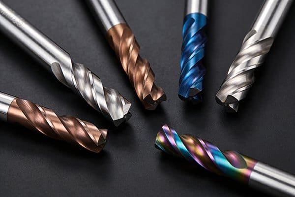
Struggling with inconsistent cuts from your end mill1? This frustration costs time and material. The secret to predictable performance lies in understanding how each part of the tool actually works.
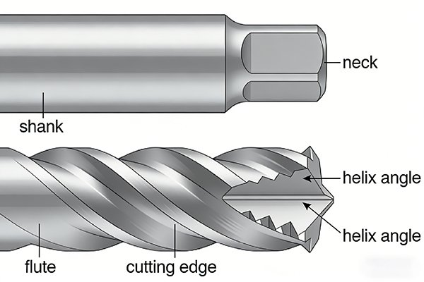
Every part of an end mill1, from the shank2 holding it to the flutes3 that cut and clear chips, plays a specific role. The shank2 provides stability, flutes3 manage chip evacuation4, and the cutting edges5 determine the finish. Understanding these components helps you select the right tool.
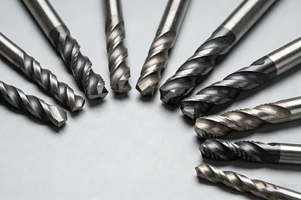
I've spent years in this industry, and I've seen firsthand how a small detail on an end mill1 can make a huge difference. It's not just a single piece of carbide; it's a system of carefully designed features working together. To really get the most out of your tools and your machine, you need to break it down piece by piece. Let's start from the very foundation of the tool and work our way to the cutting edge.
Why is the Shank the Foundation of the Entire Tool?
Experiencing chatter and poor runout6? This vibration7 can ruin your workpiece and damage your machine. The problem often isn't the cutting edge, but the tool's foundation: the shank2.
The shank2 is the end mill1's connection to the machine tool holder. It transmits all the torque and speed from the spindle. A precise, well-made shank2 ensures rigidity8, minimizes runout6, and prevents vibration7, which is absolutely essential for achieving accuracy and a good surface finish9.
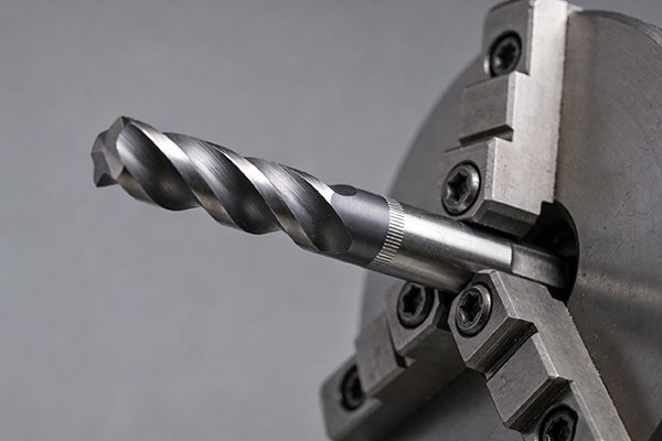
The shank2 might seem like the simplest part of an end mill1, but its job is critical. It's the bridge between the power of your machine's spindle and the cutting action at the tip. If this connection is weak or imprecise, nothing else matters. All the force and rotation from the machine flows through this small cylinder of carbide. In our factory, we pay extreme attention to the cylindricity, surface finish9, and tight tolerances of our shank2s because we know that's where a successful cut begins. A poorly ground shank2 can introduce runout6—a tiny wobble that gets magnified at the cutting tip. This wobble leads directly to chatter, poor part finish, and drastically reduced tool life10. The quality of the shank2 determines how well the tool holder can grip it, which is fundamental to the entire system's rigidity8.
Shank and Holder Systems
| Holder Type | Grip Mechanism | Key Advantage |
|---|---|---|
| Spring Collet | Mechanical Clamping | Versatile and common |
| Hydraulic Holder | Fluid Pressure | Excellent vibration7 damping |
| Heat-Shrink Holder | Thermal Expansion | Highest grip force and accuracy |
How Do Flutes and Helix Angle Work Together to Cut and Clear Chips?
Are you constantly dealing with clogged flutes3 and broken tools, especially in deep pockets? This stops your machine and ruins your part. The solution lies in the synergy between the flutes3 and the helix angle11.
Flutes are the spiral grooves that form the cutting edges5 and provide a path for chips to escape. The helix angle11 of these flutes3 determines how aggressively the tool cuts and how efficiently it ejects chips. A higher helix angle11 pulls chips up and away more effectively.
Think of the flutes3, or chip grooves, as highways for metal chips. Their job is twofold: to form the cutting edge and to get the cut material out of the way as fast as possible. If these highways get jammed, the tool will overheat, bind up, and likely break. The helix angle11 is the "steepness" of this highway. A low helix angle11 (around 30°) provides a stronger cutting edge and is great for tough materials, but it doesn't pull chips out very aggressively. A high helix angle11 (45° or more) creates a smoother, shearing cut. This action pulls chips up and out of the pocket very efficiently, which is perfect for finishing passes or machining soft materials like aluminum that produce long, stringy chips. We've tested countless helix angle11 variations to find the perfect balance for different materials, so our customers don't have to guess.
Flute Count and Helix Angle Guide
| Feature | Low Count (2-3 Flutes) | High Count (4+ Flutes) |
|---|---|---|
| Chip Clearance | Excellent | Limited |
| Core Strength | Lower | Higher |
| Best For | Aluminum, soft materials | Steels, hard materials |
| Helix Angle | High (45°+) for soft materials | Low (30°-38°) for hard materials |
What Allows an End Mill to Plunge Straight Down Like a Drill?
Ever tried to plunge an end mill1 only to have it break instantly? It’s a costly and dangerous mistake. The ability to plunge safely depends on a specific feature: its end-face geometry.
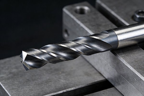
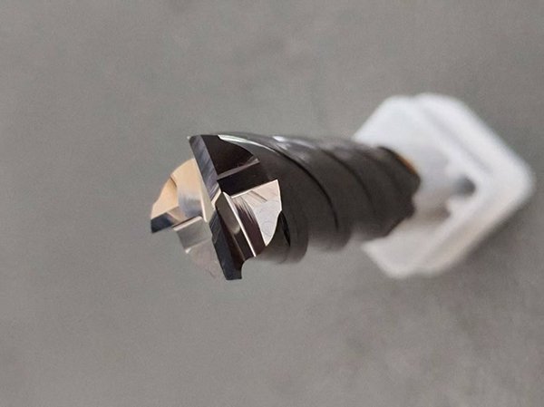
An end mill1 can plunge straight down if it is 'center-cutting12.' This means its cutting edges5 extend all the way to the center of the tool's tip. Non-center-cutting12 end mill1s have a small hole in the middle and cannot be used for plunging operations.
Not all end mill1s are created equal when it comes to plunging. If you look at the very tip of the tool, you'll see the difference. A center-cutting12 end mill1 has cutting edges5 that cross the exact center point. This allows it to shear material directly beneath it, just like a drill bit. You need this feature for any operation where the tool enters the material vertically, such as creating a pocket from solid or drilling a hole. A non-center-cutting13g](https://nv-tool.com/how-do-you-decide-between-a-slot-mill-and-an-end-mill-for-maximum-performance/)%%%FOOTNOTE_REF_12%%% end mill1 has a small hole or gap at its center. If you try to plunge with this tool, the material in the center has nowhere to go. It will push against the tool with immense force until the tool snaps. I remember a new machinist who kept breaking tools trying to make a pocket. A quick look at the end mill1's tip revealed the problem. It's a simple check that saves a lot of headaches and money.
Plunging Capability
| Tool Type | Center Geometry | Plunging Ability | Primary Use |
|---|---|---|---|
| Center-Cutting | Edges cross the center | Yes | Plunging, pocketing, slotting |
| Non-Center-Cutting | Hole/gap at the center | No | Side milling, profiling |
How Do Cutting Diameter and Flute Length Define Your Machining Limits?
Choosing the right size end mill1 can be tricky. A tool that's too long will chatter and break, while one that's too short won't reach. It's all about balancing the cutting diameter14 with the length of cut.
The cutting diameter14 determines the width of the cut. The flute length15, or length of cut (LOC), dictates the maximum axial depth you can machine in a single pass. A longer LOC allows for deeper walls, but it also reduces the tool's rigidity8, increasing the risk of deflection.
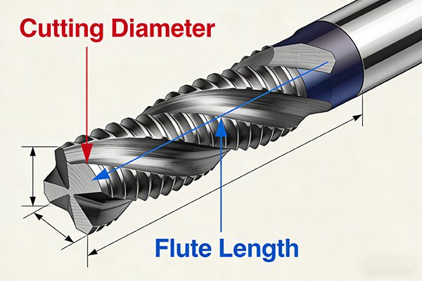
The two most basic dimensions of an end mill1—its diameter and its flute length15—set the absolute physical boundaries of your operation. The diameter is simple: it defines how wide of a slot you can make. The length of cut (LOC) is more complicated. It tells you the deepest wall you can machine in one go. However, there's a critical trade-off here: rigidity8. The longer a tool is relative to its diameter, the more it will want to bend and vibrate under cutting forces. This is called deflection, and it's the enemy of precision and tool life10. As a rule, you should always use the shortest possible tool that can do the job. A short, stubby tool is incredibly rigid and can handle much more aggressive cutting parameters than a long, skinny one. At NV-Tool, we offer standard, extended, and extra-long length options, but we always advise our clients to start with the shortest tool first. Rigidity is king in machining.
Length-to-Diameter Ratio and Rigidity
| L:D Ratio | Rigidity | Recommended Use |
|---|---|---|
| 3:1 or less | Very High | Aggressive roughing, high-speed machining |
| 5:1 | Good | General purpose, moderate depth |
| 8:1 or more | Low | Finishing, deep pockets (requires reduced parameters) |
Where is the "Sharpness" of an End Mill Actually Defined?
Think a sharp-looking edge guarantees performance? But when it wears out fast or leaves a bad finish, it's confusing. Real tool performance comes from the microscopic geometry of the cutting edge.
The sharpness of an end mill1 isn't just a razor edge. It's defined by the rake angle16, which controls cutting force, and the clearance angle17, which prevents rubbing. A tiny, reinforced 'cutting edge band18' provides strength, preventing the edge from chipping immediately under pressure.
When we talk about a tool's "sharpness," we're really talking about a sophisticated system of angles ground onto the carbide. The most important of these are the rake and clearance angle17s. The rake angle16 is the angle of the cutting face; a positive rake angle16 helps "peel" the chip away smoothly, reducing cutting forces, which is great for softer materials. The clearance angle17 is the space ground away behind the cutting edge. Without it, the back of the tool would rub against the freshly cut surface, creating immense friction and heat. But the secret to a durable edge is a feature called the cutting edge band18, or land. It's a very narrow, flat surface right behind the cutting edge. It makes the edge much stronger and less likely to chip under pressure. An edge that is too sharp, like a razor blade, would break instantly in steel. It's this balance of sharpness from the rake angle16 and strength from the land that defines a high-performance cutting tool.
Key Cutting Edge Geometries
| Geometry | Function | Impact on Performance |
|---|---|---|
| Rake Angle | Controls chip formation | Affects cutting force and power consumption |
| Clearance Angle | Prevents rubbing/friction | Reduces heat and improves surface finish9 |
| Cutting Edge Band | Strengthens the cutting edge | Prevents chipping and increases tool life10 |
| Tip Fillet (Radius) | Reinforces the corner | Dramatically improves strength and prevents corner wear |
Conclusion
From the shank2's solid grip to the precise angles of its cutting edge, every part of an end mill1 matters. Understanding this anatomy helps you choose better tools and achieve superior results.
Explore this resource to understand the fundamentals of end mills and their applications in machining. ↩
Learn about the critical function of the shank in ensuring tool stability and performance. ↩
Discover how flutes contribute to chip evacuation and cutting efficiency in machining. ↩
Discover the importance of effective chip removal for maintaining tool life and performance. ↩
Explore the various cutting edge designs and their impact on machining performance. ↩
Understand the concept of runout and its implications for precision machining. ↩
Learn about the effects of vibration on tool performance and how to mitigate it. ↩
Discover how rigidity affects tool performance and precision in machining. ↩
Understand the relationship between end mill features and the quality of surface finish. ↩
Learn strategies to enhance tool life and performance in machining operations. ↩
Understand how helix angle influences cutting action and chip removal for better machining results. ↩
Learn about the benefits of center-cutting end mills for various machining operations. ↩
Explore the applications and limitations of non-center-cutting end mills in machining. ↩
Understand the relationship between cutting diameter and the width of cuts in machining. ↩
Learn about the significance of flute length in determining machining depth and rigidity. ↩
Explore the role of rake angle in chip formation and cutting efficiency. ↩
Learn how clearance angle prevents friction and improves surface finish in machining. ↩
Understand the function of the cutting edge band in enhancing tool durability. ↩