Are your carbide tools1 underperforming? This leads to poor finishes, broken tools, and wasted money. Finding the right balance between speed and feed is the key to fixing this.
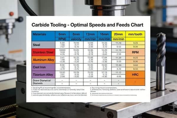
The optimal speeds and feeds for carbide tools1 depend on your material, tool type, and machine setup. The goal is to balance cutting speed2 (Vc) and feed rate3 (f) to achieve the highest metal removal rate4 while protecting the tool and getting a good surface finish.
Getting your parameters right can seem complicated. I've been in countless machine shops and seen the frustration firsthand. But the truth is, it's a logical process that anyone can learn. It all starts with understanding a few basic factors that influence every cut you make. Let's break it down together, so you can make your machining more efficient and profitable. This is how you turn a good process into a great one.
What Factors Determine the Right Speeds and Feeds for Carbide Tools?
Do you wonder why the same tool works perfectly on one job but fails on another? Using generic settings is a gamble that can damage your workpiece, your machine, and your tools. The secret is knowing what factors to consider for each unique setup.
The most important factors are the workpiece material, the tool's carbide grade and coating, tool diameter5, machine rigidity6, and your cooling method. Each of these plays a huge role in finding the sweet spot for your speeds and feeds. Paying attention to them will save you headaches.

Let's dive deeper into these factors. In my experience, over 90% of tooling problems come from a mismatch in one of these areas. It’s not just about plugging numbers into a calculator. You need to understand why these factors matter. For example, the material you are cutting is the biggest variable. Cutting a soft material like aluminum allows for very high speeds, but if you try those same speeds on hardened tool steel, you will destroy your tool instantly. The rigidity of your machine is another critical point. An older, less rigid machine will vibrate under a heavy cut, which we call chatter7. This chatter7 will chip the cutting edge8 of your tool. On the other hand, a modern, rigid machine allows you to push the tools much harder. At NV-Tool, we also use advanced PVD coatings9 like our T600 and W600 series. These coatings act as a shield, allowing the tool to run faster and hotter without breaking down.
| Factor | Influence on Speeds and Feeds | Why It Matters |
|---|---|---|
| Workpiece Material | Harder materials require lower speeds. | Prevents excessive heat and tool wear10. |
| Tool Coating | Advanced coatings allow for higher speeds. | Increases heat resistance and lubricity. |
| Machine Rigidity | Less rigid machines need lower speeds/feeds. | Prevents vibration (chatter7) and tool chipping. |
| Coolant Use | Proper coolant allows for higher parameters. | Removes heat and evacuates chips effectively. |
| Tool Diameter | Smaller tools need higher RPM for the same Vc. | Maintains the correct surface speed. |
How Do You Calculate Speeds and Feeds for Different Materials?
Do you find yourself guessing your speeds and feeds for a new job? This guessing game leads to inconsistent results, broken tools, and lost production time. There is a simple and logical process for calculating your starting parameters every time.
The basic calculation starts with finding the right Cutting Speed (Vc) for your material. You use this to calculate your Spindle Speed (n). Then, you use the Feed per Tooth (fz) to find your final Feed Rate (F). The main formula is: Spindle Speed (n) = (Vc 1000) / (π Tool Diameter).

Let's walk through this process step-by-step. This is the exact logic we teach our new customers.
First, you determine the Cutting Speed (Vc). This is the surface speed at which the cutting edge8 moves across the material, measured in meters per minute (m/min). This value is not random. It comes from charts provided by tool manufacturers like us. It is based on thousands of hours of testing. For example, a good starting Vc for milling mild steel with one of our coated carbide end mills might be 120 m/min.
Second, you calculate the Spindle Speed (n). This is the RPM your machine spindle needs to turn. You use the formula: n = (Vc * 1000) / (π * D). Here, 'D' is the diameter of your tool in millimeters. For a 10mm end mill cutting steel at Vc 120, the calculation is (120 * 1000) / (3.14159 * 10) = 3820 RPM.
Third, you determine the Feed per Tooth (fz). This is the amount of material each cutting edge8 (or flute) removes in one rotation. This also comes from a chart. For our 10mm end mill in steel, a good starting fz might be 0.05 mm/tooth.
Finally, you calculate the machine's Feed Rate (F). The formula is: F = n * fz * Z, where 'Z' is the number of teeth on the tool. If our end mill has 4 teeth, the calculation is 3820 * 0.05 * 4 = 764 mm/min. This is the feed rate3 you program into your machine.
| Material | Example Vc (m/min) | Example fz (mm/tooth) |
|---|---|---|
| Aluminum | 250 - 500 | 0.08 - 0.15 |
| Mild Steel | 100 - 180 | 0.04 - 0.08 |
| Stainless Steel | 70 - 120 | 0.03 - 0.06 |
| Hardened Steel (>50HRC) | 40 - 80 | 0.02 - 0.05 |
What Are the Recommended Parameters for Common Carbide Tool Types?
Are you using the same general settings for your drills, end mills, and turning tools? This is a common mistake that limits your performance. Each tool is designed for a specific task and requires its own unique approach to speeds and feeds. Let's look at some starting points.
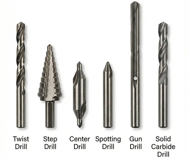
End mills rely on a balance of spindle speed11 and a specific chip load12 per tooth. Drills focus on spindle speed11 and feed per revolution, where chip evacuation is key. Turning inserts use surface speed based on the workpiece diameter. Each requires a different mindset for programming.
I often see customers struggle because they apply milling logic to a drilling operation. It just doesn't work. Let's clarify the differences.
Solid Carbide End Mills: With tools like our 4-flute HRC55 series, the most important parameter after Vc is the chip load12 (fz). If your chip load12 is too small, the flutes will rub against the material instead of cutting it. This creates a lot of heat and wears the tool out fast. If the chip load12 is too large, you risk breaking the tool. The goal is to create a nice, clean chip.
Carbide Drills: For our 3D and 5D carbide drills13, the key parameters are cutting speed2 (Vc) and feed per revolution (fn). Unlike milling, you are not calculating a feed per tooth14. Chip evacuation is the biggest challenge here. This is why our drills with internal coolant channels perform so well. The coolant blasts chips out of the hole, allowing you to run much higher feed rate3s without jamming.
Turning Inserts: When you are turning on a lathe with our CNMG or WNMG inserts, the cutting speed2 calculation is different. The "diameter" in the formula is the diameter of the workpiece, not the tool. The feed is also expressed as a feed per revolution (mm/rev), which determines the surface finish. A lower feed rate3 gives a smoother finish.
| Tool Type | Key Parameter 1 | Key Parameter 2 | Common Application |
|---|---|---|---|
| End Mill | Cutting Speed (Vc) | Feed per Tooth (fz) | Profiling, Pocketing, Slotting |
| Drill | Cutting Speed (Vc) | Feed per Revolution (fn) | Hole making |
| Turning Insert | Cutting Speed (Vc) | Feed per Revolution (fn) | OD/ID Turning, Facing |
| Threading Tool | Spindle Speed (RPM) | Pitch | Creating threads |
How Do You Optimize Performance and Extend Tool Life?
Are your brand-new carbide tools1 wearing out way too fast? Constantly replacing tools eats into your profits and causes a lot of expensive downtime. You can make simple adjustments to your process to make every tool last much longer and perform better.
Start with the recommended parameters from your tool supplier, then adjust based on what you see and hear. Listen for bad sounds like chatter7, check the color of your chips, and inspect the tool for wear. Small, 10% adjustments to speed or feed can make a huge difference.
Optimization is an active process. You can't just set the parameters and walk away. You need to become a detective at the machine.
First, use your ears. A machine running well has a smooth, consistent sound. A high-pitched squeal often means your speed is too high or your feed is too low, causing the tool to rub. A loud, rhythmic banging or rumbling sound is chatter7. This is very destructive and means you need to reduce your depth of cut, change your RPM, or check your tool holding.
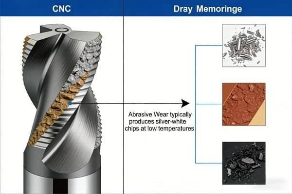
Second, look at the chips. Your chips tell a story. For steel, you want to see small, broken chips that are a light straw or silver color. If your chips are blue, black, or purple, you have too much heat. You need to lower your cutting speed2 (Vc) or improve your coolant. If you are getting long, stringy chips that wrap around the tool, you should increase your feed rate3.
Third, inspect the tool. After a run, take the tool out and look at the cutting edge8. A small, even wear land along the edge is normal. If you see tiny chips or fractures on the edge, your feed is likely too high or you have instability (chatter7). If you see material welded onto the cutting edge8 (called a built-up edge), your cutting speed2 is too low.
As a general rule, we tell our customers to find a stable process with our recommended starting values. Then, try increasing the feed rate3 by 10%. If the machine sounds good and the chips look good, you've just increased your productivity by 10%. You can continue this process until you find the true limit. This is how you maximize your investment in high-quality tools from us at NV-Tool.
Conclusion
Mastering speeds and feeds is about finding the right balance. Start with good data, calculate correctly, and then listen and watch to optimize. This simple process will boost your productivity.
Explore expert insights on maximizing the performance and lifespan of carbide tools. ↩
Learn how to calculate and adjust cutting speeds for various materials effectively. ↩
Understand how feed rate impacts tool performance and surface finish. ↩
Discover the key elements that affect metal removal rates for better efficiency. ↩
Find out how tool diameter plays a crucial role in speed and feed calculations. ↩
Explore the significance of machine rigidity in achieving optimal machining results. ↩
Understand the causes of chatter and strategies to minimize its impact on machining. ↩
Learn effective methods for assessing tool wear to maintain machining quality. ↩
Discover the advantages of PVD coatings for improved tool durability and efficiency. ↩
Learn to identify tool wear signs to optimize your machining processes. ↩
Get insights on calculating spindle speed for various tools and materials. ↩
Understand the importance of chip load in achieving efficient cutting. ↩
Learn about the specific parameters that enhance the performance of carbide drills. ↩
Understand the concept of feed per tooth and its impact on machining efficiency. ↩